
SUPPORT AND SERVICE Offering On-line Pre-and-Post Service and Support
FAQ
GARP VLAN registration protocol (GVRP) can exchange VLAN configuration information dynamically. When the switch receives VLAN information and GARP VLAN Registration Protocol, the receiving interface joins that VLAN. If an interface VLAN does not exist , the switch will creates the VLAN automatically.
The GVRP max member of automatically creates the VLAN is 256.
Support Models
ECS4620 series, ECS4510 series, ECS4120 series, ECS4100 series, ECS5520 series, ECS4530 series, ECS2100 series, ECS2110 series, ECS3510 series

4100 switch1 config:
Console#configure
Console(config)#vlan database
Console(config-vlan)#vlan 10,20,30
Console(config-vlan)#exit
Console(config)#interface vlan 10
Console(config-if)#interface vlan 20
Console(config-if)#interface vlan 30
Console(config-if)#exit
Console(config)#bridge-ext gvrp
Console(config)#interface ethernet 1/1
Console(config-if)#switchport gvrp
Console(config-if)#exit
Console(config)#interface ethernet 1/11
Console(config-if)#switchport allowed vlan add 10,20,30
4100 switch2 config:
Console#configure
Console(config)#bridge-ext gvrp
Console(config)#interface ethernet 1/1
Console(config-if)#switchport gvrp
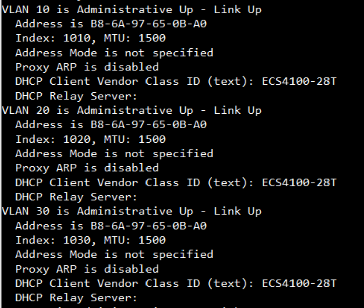
Show ip interface to check VLAN on 4100 switch1 :
VLAN 10,20,30 Administrative up must be Link Up status
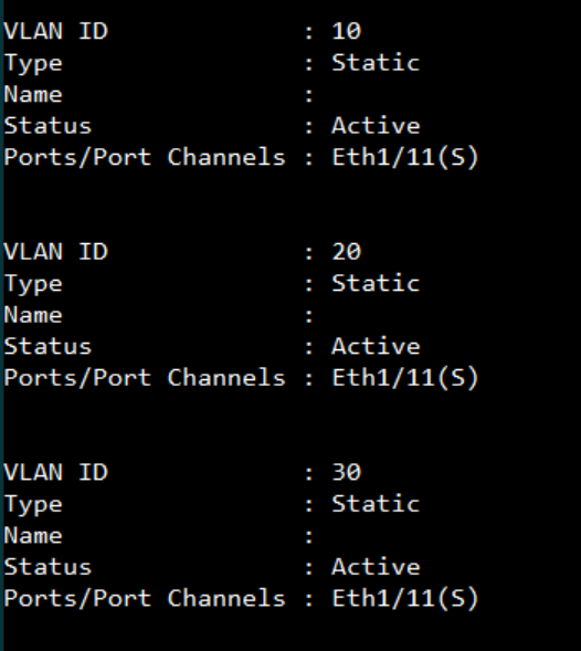
Show vlan on 4100 switch1 :
VLAN 10,20,30 type should be static
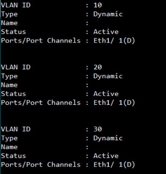
Show vlan on 4100 switch2 :
VLAN 10,20,30 type should be Dynamic
The BGP(Border Gateway Protocol) is to exchange network reachability information with other BGP systems.This network reachability information includes information on the list of Autonomous Systems (ASes).
IBGP(Internal BGP) means the connection between internal peer that is in the same Autonomous System as the local system. EBGP(External BGP) means the connection between external peer that is in a different Autonomous System than the local system.
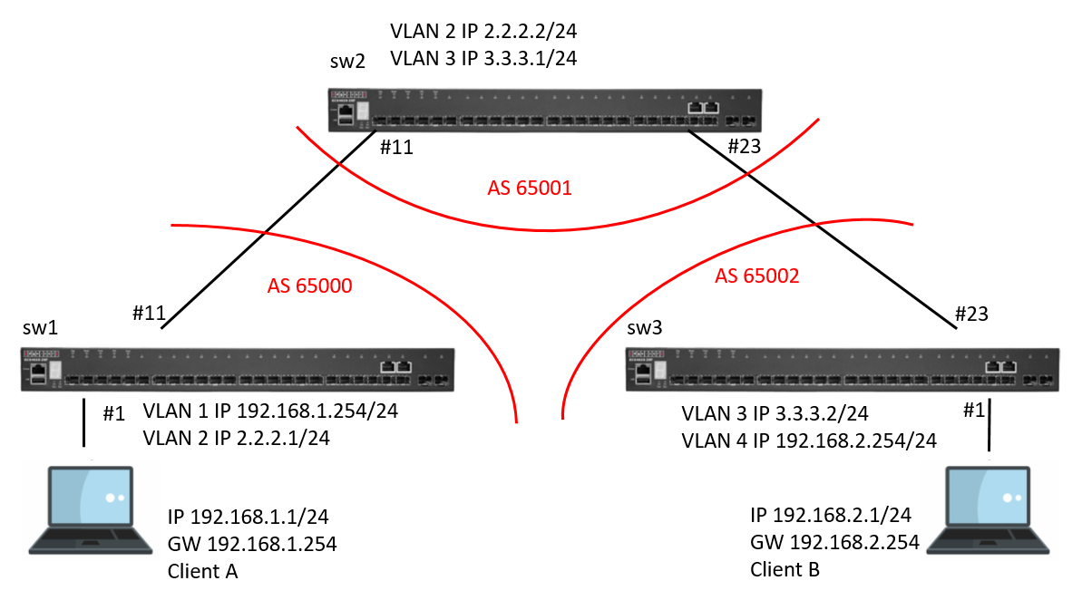
Scenario:
Procedure:
Switch_01 Configuration:
Step 1: BGP global config. Apply VLAN on port and configure VLAN's IP address.
sw1#
sw1#configure
sw1(config)#router bgp 65000
sw1(config-router)#network 192.168.1.0 255.255.255.0
sw1(config-router)#neighbor 2.2.2.2 remote-as 65001
sw1(config-router)#exit
sw1(config)#vlan database
sw1(config-vlan)#vlan 2
sw1(config-vlan)#exit
sw1(config)#interface vlan 1
sw1(config-if)#ip address 192.168.1.254/24
sw1(config-if)#exit
sw1(config)#interface vlan 2
sw1(config-if)#ip address 2.2.2.1/24
sw1(config-if)#
sw1(config-if)#exit
sw1(config)#interface ethernet 1/11
sw1(config-if)#switchport allowed vlan add 2
sw1(config-if)#switchport native vlan 2
sw1(config-if)#
Switch_02 Configuration:
Step 1: BGP global config. Apply VLAN on port and configure VLAN's IP address.
sw2#
sw2#configre
sw2(config)#router bgp 65001
sw2(config-router)#network 2.2.2.0 255.255.255.0
sw2(config-router)#network 3.3.3.0 255.255.255.0
sw2(config-router)#neighbor 2.2.2.1 remote-as 65000
sw2(config-router)#neighbor 3.3.3.2 remote-as 65002
sw2(config-router)#exit
sw2(config)#vlan database
sw2(config-vlan)#vlan 2,3
sw2(config-vlan)#exit
sw2(config)#interface vlan 2
sw2(config-if)#ip address 2.2.2.2/24
sw2(config)#interface vlan 3
sw2(config-if)#ip address 3.3.3.1/24
sw2(config-if)#
sw2(config-if)#exit
sw2(config)#interface ethernet 1/11
sw2(config-if)#switchport allowed vlan add 2
sw2(config-if)#switchport native vlan 2
sw2(config-if)#
sw2(config)#interface ethernet 1/23
sw2(config-if)#switchport allowed vlan add 3
sw2(config-if)#switchport native vlan 3
sw2(config-if)#
Switch_03 Configuration:
Step 1: BGP global config. Apply VLAN on port and configure VLAN's IP address.
sw3#
sw3#configre
sw3(config)#router bgp 65002
sw3(config-router)#network 192.168.2.0 255.255.255.0
sw3(config-router)#neighbor 3.3.3.1 remote-as 65001
sw3(config-router)#exit
sw3(config)#vlan database
sw3(config-vlan)#vlan 3,4
sw3(config-vlan)#exit
sw3(config)#interface vlan 3
sw3(config-if)#ip address 3.3.3.2/24
sw3(config-if)#exit
sw3(config)#interface vlan 4
sw3(config-if)#ip address 192.168.2.254/24
sw3(config-if)#
sw3(config-if)#exit
sw3(config)#interface ethernet 1/1
sw3(config-if)#switchport allowed vlan add 4
sw3(config-if)#switchport native vlan 4
sw3(config)#interface ethernet 1/23
sw3(config-if)#switchport allowed vlan add 3
sw3(config-if)#switchport native vlan 3
sw3(config-if)#
bgp status:
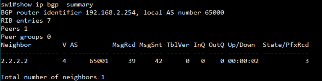
SW1:
display the AS number and neighbor
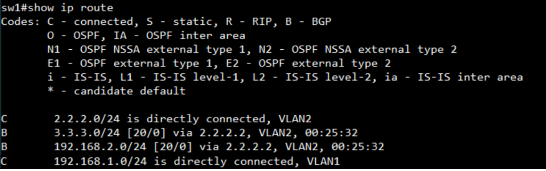
display the routing table
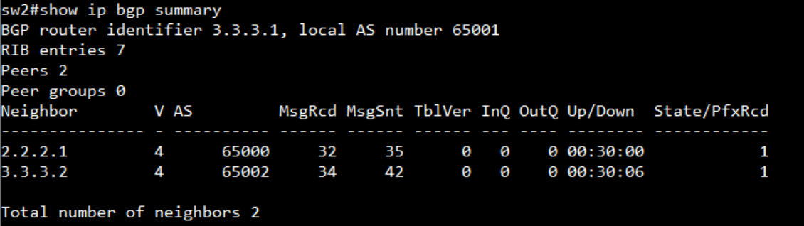
SW2:
display the AS number and neighbor
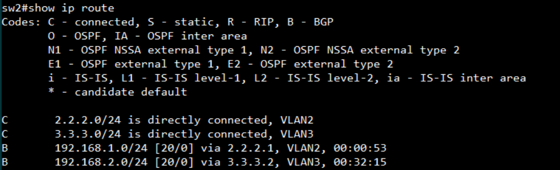
display the routing table
SW3:
display the AS number and neighbor
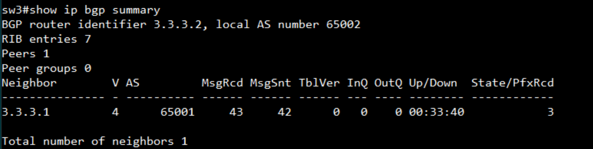
display the routing table
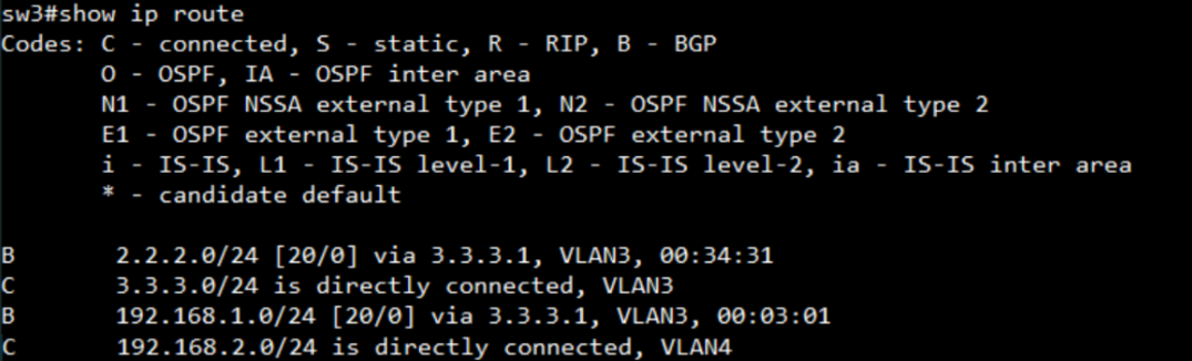
Scenario:
Configuration on SW1:
Setup VLAN
SW1#configure
SW1(config)#interface ethernet 1/1
SW1(config-if)#switchport allowed vlan add 10 untagged
SW1(config-if)#switchport native vlan 10
SW1(config-if)#switchport allowed vlan remove 1
SW1(config-if)#interface ethernet 1/12
SW1(config-if)#switchport allowed vlan add 20 untagged
SW1(config-if)#switchport native vlan 20
SW1(config-if)#switchport allowed vlan remove 1
SW1(config-if)#interface vlan 10
SW1(config-if)#ip address 192.168.10.254/24
SW1(config-if)#interface vlan 20
SW1(config-if)#ip address 192.168.20.1/24
SW1(config-if)#end
Enable OSPF
SW1#configure
SW1(config)#router ospf 1
SW1(config-router)#network 192.168.10.0 255.255.255.0 area 0
SW1(config-router)#network 192.168.20.0 255.255.255.0 area 0
SW1(config-router)#end
Enable Multicast Routing and PIM
SW1#configure
SW1(config)#ip multicast-routing
Note: IPv6 multicast routing will also be enabled.
SW1(config)#router pim
SW1(config-router)#end
Enable IGMP and PIM Dense-Mode on VLAN
SW1#configure
SW1(config)#interface vlan 10
SW1(config-if)#ip igmp
SW1(config-if)#ip pim dense-mode
SW1(config-if)#interface vlan 20
SW1(config-if)#ip igmp
SW1(config-if)#ip pim dense-mode
SW1(config-if)#end
Configuration on SW2:
Setup VLAN
SW2#configure
SW2(config)#interface ethernet 1/1
SW2(config-if)#switchport allowed vlan add 30 untagged
SW2(config-if)#switchport native vlan 30
SW2(config-if)#switchport allowed vlan remove 1
SW2(config-if)#interface ethernet 1/12
SW2(config-if)#switchport allowed vlan add 20 untagged
SW2(config-if)#switchport native vlan 20
SW2(config-if)#switchport allowed vlan remove 1
SW2(config-if)#interface vlan 30
SW2(config-if)#ip address 192.168.30.254/24
SW2(config-if)#interface vlan 20
SW2(config-if)#ip address 192.168.20.2/24
SW2(config-if)#end
Enable OSPF
SW2#configure
SW2(config)#router ospf 1
SW2(config-router)#network 192.168.30.0 255.255.255.0 area 0
SW2(config-router)#network 192.168.20.0 255.255.255.0 area 0
SW2(config-router)#end
Enable Multicast Routing and PIM
SW2#configure
SW2(config)#ip multicast-routing
Note: IPv6 multicast routing will also be enabled.
SW2(config)#router pim
SW2(config-router)#end
Enable IGMP and PIM Dense-Mode on VLAN
SW2#configure
SW2(config)#interface vlan 30
SW2(config-if)#ip igmp
SW2(config-if)#ip pim dense-mode
SW2(config-if)#interface vlan 20
SW2(config-if)#ip igmp
SW2(config-if)#ip pim dense-mode
SW2(config-if)#end
Test Result:
SW1,
Display PIM status and PIM neighbor for the specified interface
SW1#show ip pim interface
PIM is enabled.
VLAN 1 is down.
PIM Mode : Unspecified

VLAN 10 is up.
PIM Mode              : Dense Mode
IP Address            : 192.168.10.254
Hello Interval        : 30 sec
Hello HoldTime        : 105 sec
Triggered Hello Delay : 5 sec
Join/Prune Holdtime   : 210 sec
Lan Prune Delay       : Disabled
Propagation Delay     : 500 ms
Override Interval     : 2500 ms
Graft Retry Interval  : 3 sec
Max Graft Retries     : 3
State Refresh Ori Int : 60 sec

VLAN 20 is up.
PIM Mode              : Dense Mode
IP Address            : 192.168.20.1
Hello Interval        : 30 sec
Hello HoldTime        : 105 sec
Triggered Hello Delay : 5 sec
Join/Prune Holdtime   : 210 sec
Lan Prune Delay       : Disabled
Propagation Delay     : 500 ms
Override Interval     : 2500 ms
Graft Retry Interval  : 3 sec
Max Graft Retries     : 3
State Refresh Ori Int : 60 sec

SW1#show ip pim neighbor
Neighbor Address VLAN Interface Uptime (sec.) Expiration Time (sec)  DR
---------------- -------------- ------------- --------------------- ---
192.168.20.2/32  20             00:49:11                   00:01:35 Yes
Display the multicast information for the specified interface
SW1#show ip igmp interface
VLAN 1                           : down
IGMP                             : Disabled
IGMP Proxy                       : Disabled
IGMP Version                     : 2
IGMP Unsolicited Report Interval : 400 sec
Robustness Variable              : 2
Query Interval                   : 125 sec
Query Max Response Time          : 100 (resolution in 0.1 sec)
Last Member Query Interval       : 10 (resolution in 0.1 sec)
Querier                          : 0.0.0.0
Joined Groups :
Static Groups :
VLAN 10                          : up
IGMP                             : Enabled
IGMP Proxy                       : Disabled
IGMP Version                     : 2
IGMP Unsolicited Report Interval : 400 sec
Robustness Variable              : 2
Query Interval                   : 125 sec
Query Max Response Time          : 100 (resolution in 0.1 sec)
Last Member Query Interval       : 10 (resolution in 0.1 sec)
Querier                          : 192.168.10.254
Joined Groups :
239.255.255.250
Static Groups :
VLAN 20                          : up
IGMP                             : Enabled
IGMP Proxy                       : Disabled
IGMP Version                     : 2
IGMP Unsolicited Report Interval : 400 sec
Robustness Variable              : 2
Query Interval                   : 125 sec
Query Max Response Time          : 100 (resolution in 0.1 sec)
Last Member Query Interval       : 10 (resolution in 0.1 sec)
Querier                          : 192.168.20.1
Joined Groups :
Static Groups :
SW1#show ip igmp groups

GroupAddress     Interface Vlan  Last Reporter   Uptime   Expire   V1 Timer
--------------- --------------- --------------- -------- -------- ---------
239.255.255.250              10    192.168.10.1   0:56:7   0:2:59     0:0:0
Display the information in the routing table
SW1#show ip route
Codes: C - connected, S - static, R - RIP, B - BGP
O - OSPF, IA - OSPF inter area
N1 - OSPF NSSA external type 1, N2 - OSPF NSSA external type 2
E1 - OSPF external type 1, E2 - OSPF external type 2
i - IS-IS, L1 - IS-IS level-1, L2 - IS-IS level-2, ia - IS-IS inter area
* - candidate default

C 192.168.10.0/24 is directly connected, VLAN10
C 192.168.20.0/24 is directly connected, VLAN20
O 192.168.30.0/24 [110/2] via 192.168.20.2, VLAN20, 00:02:43
Display the IPv4 multicast routing table
SW1#show ip mroute

IP Multicast Forwarding is enabled.

IP Multicast Routing Table
Flags: D - Dense, S - Sparse, s - SSM Channel, C - Connected, P - Pruned,
F - Register flag, R - RPT-bit set, T - SPT-bit set, J - Join SPT
Interface state: F - Forwarding, P - Pruned, L - Local

(192.168.10.1, 224.1.1.1), uptime 00:27:09, stat expires 00:02:16
Owner: PIM-DM, Flags: DC
Incoming interface: VLAN 10
Outgoing interface list:
VLAN20 (F)
(192.168.30.1, 239.255.255.250), uptime 00:02:54
Owner: PIM-DM, Flags: D
Incoming interface: VLAN 20, RPF neighbor: 192.168.20.2
Outgoing interface list:
VLAN10 (F) ,
SW2,
Display PIM status and PIM neighbor for the specified interface
SW2#show ip pim interface
PIM is enabled.
VLAN 1 is down.
PIM Mode : Unspecified

VLAN 20 is up.
PIM Mode              : Dense Mode
IP Address            : 192.168.20.2
Hello Interval        : 30 sec
Hello HoldTime        : 105 sec
Triggered Hello Delay : 5 sec
Join/Prune Holdtime   : 210 sec
Lan Prune Delay       : Disabled
Propagation Delay     : 500 ms
Override Interval     : 2500 ms
Graft Retry Interval  : 3 sec
Max Graft Retries     : 3
State Refresh Ori Int : 60 sec

VLAN 30 is up.
PIM Mode              : Dense Mode
IP Address            : 192.168.30.254
Hello Interval        : 30 sec
Hello HoldTime        : 105 sec
Triggered Hello Delay : 5 sec
Join/Prune Holdtime   : 210 sec
Lan Prune Delay       : Disabled
Propagation Delay     : 500 ms
Override Interval     : 2500 ms
Graft Retry Interval  : 3 sec
Max Graft Retries     : 3
State Refresh Ori Int : 60 sec

SW2#show ip pim neighbor
Neighbor Address VLAN Interface Uptime (sec.) Expiration Time (sec)  DR
---------------- -------------- ------------- --------------------- ---
192.168.20.1/32  20             00:52:26                   00:01:23
Display the multicast information for the specified interface
SW2#show ip igmp interface
VLAN 1                           : down
IGMP                             : Disabled
IGMP Proxy                       : Disabled
IGMP Version                     : 2
IGMP Unsolicited Report Interval : 400 sec
Robustness Variable              : 2
Query Interval                   : 125 sec
Query Max Response Time          : 100 (resolution in 0.1 sec)
Last Member Query Interval       : 10 (resolution in 0.1 sec)
Querier                          : 0.0.0.0
Joined Groups :
Static Groups :
VLAN 20                          : up
IGMP                             : Enabled
IGMP Proxy                       : Disabled
IGMP Version                     : 2
IGMP Unsolicited Report Interval : 400 sec
Robustness Variable              : 2
Query Interval                   : 125 sec
Query Max Response Time          : 100 (resolution in 0.1 sec)
Last Member Query Interval       : 10 (resolution in 0.1 sec)
Querier                          : 192.168.20.1
Joined Groups :
Static Groups :
VLAN 30                          : up
IGMP                             : Enabled
IGMP Proxy                       : Disabled
IGMP Version                     : 2
IGMP Unsolicited Report Interval : 400 sec
Robustness Variable              : 2
Query Interval                   : 125 sec
Query Max Response Time          : 100 (resolution in 0.1 sec)
Last Member Query Interval       : 10 (resolution in 0.1 sec)
Querier                          : 192.168.30.254
Joined Groups :
224.1.1.1
239.255.255.250
Static Groups :
SW2#show ip igmp groups

GroupAddress     Interface Vlan  Last Reporter   Uptime   Expire   V1 Timer
--------------- --------------- --------------- -------- -------- ---------
224.1.1.1                    30    192.168.30.1   0:5:26   0:3:35     0:0:0
239.255.255.250              30    192.168.30.1   0:5:28   0:3:28     0:0:0
Display the information in the routing table
SW2#show ip route
Codes: C - connected, S - static, R - RIP, B - BGP
O - OSPF, IA - OSPF inter area
N1 - OSPF NSSA external type 1, N2 - OSPF NSSA external type 2
E1 - OSPF external type 1, E2 - OSPF external type 2
i - IS-IS, L1 - IS-IS level-1, L2 - IS-IS level-2, ia - IS-IS inter area
* - candidate default

O 192.168.10.0/24 [110/2] via 192.168.20.1, VLAN20, 00:06:38
C 192.168.20.0/24 is directly connected, VLAN20
C 192.168.30.0/24 is directly connected, VLAN30
Display the IPv4 multicast routing table
SW2#show ip mroute

IP Multicast Forwarding is enabled.

IP Multicast Routing Table
Flags: D - Dense, S - Sparse, s - SSM Channel, C - Connected, P - Pruned,
F - Register flag, R - RPT-bit set, T - SPT-bit set, J - Join SPT
Interface state: F - Forwarding, P - Pruned, L - Local

(192.168.10.1, 224.1.1.1), uptime 00:06:53
Owner: PIM-DM, Flags: D
Incoming interface: VLAN 20, RPF neighbor: 192.168.20.1
Outgoing interface list:
VLAN30 (F)
(192.168.30.1, 239.255.255.250), uptime 00:07:39, stat expires 00:02:42
Owner: PIM-DM, Flags: D
Incoming interface: VLAN 30
Outgoing interface list:
VLAN20 (F) ,
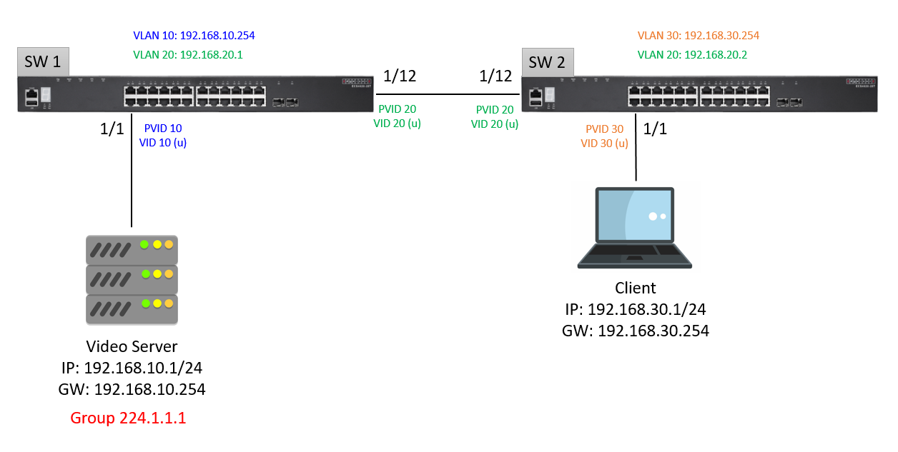
Port Trunking application scenario
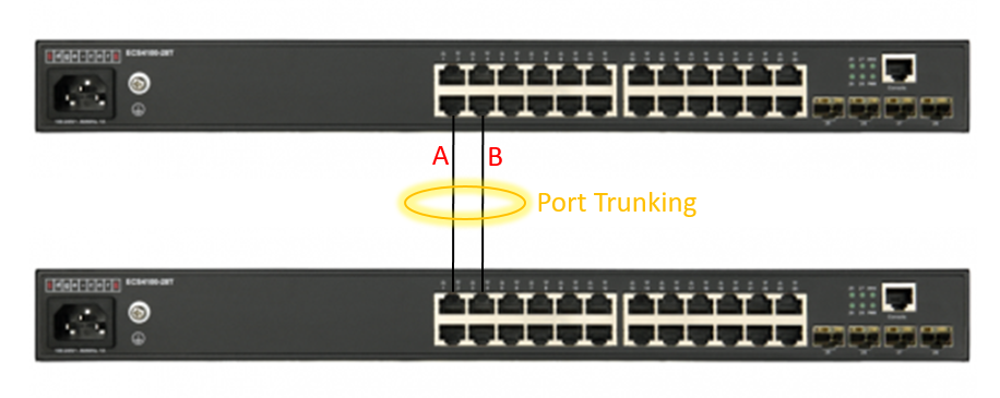
Foreword
People often ask, why can't I achieve transmission theoretical value after enabling "Link Aggregation/Port-Channel" load balance ? Even, the packet traffic always was sent on port A?
We have to know: port channel load balance is based on the "Hash mechanism" to select which port to transmit packet.
Support Models
ECS4620 series, ECS4510 series, ECS4120 series, ECS4100 series, ECS5520 series, ECS4530 series, ECS2100 series, ECS2110 series, ECS3510 series
Edgecore valid load-balancing hash values are as follows
dst-ip distribution on the destination IP address
dst-mac distribution on the destination MAC address
src-dst-ip distribution on the source and destination IP address (SIP XOR DIP)
src-dst-mac distribution on the source and destination MAC address (SA XOR DA)
src-ip distribution on the source IP address
src-mac distribution on the source MAC address
Default hash value
src-dst-mac
CLI
Setup load balance to src-dst-mac mode:
Console#config

Console(config)#port-channel load-balance ?

  dst-ip       Selection based on destination IP address

  dst-mac      Selection based on destination MAC address

  src-dst-ip   Selection based on source and destination IP address

  src-dst-mac  Selection based on source and destination MAC address

  src-ip       Selection based on source IP address

  src-mac      Selection based on source MAC address

Console(config)#port-channel load-balance src-dst-mac

Console(config)#exit
Show load balance type of switch:
Console#show port-channel load-balance

Trunk Load Balance Mode: Source and destination MAC address
Hands-on
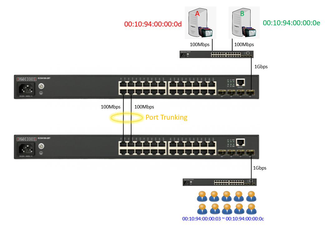
This is general application, client download file from server, we use TestCenter to simulate an experiment via port-channel load-balance “src-dst-mac” and “src-mac”, then compare the differences.
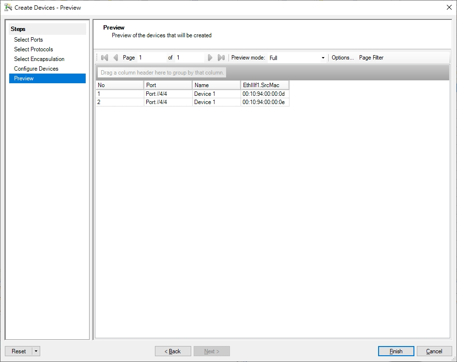
TestCenter Port 4/4
- Simulate file server A and B.
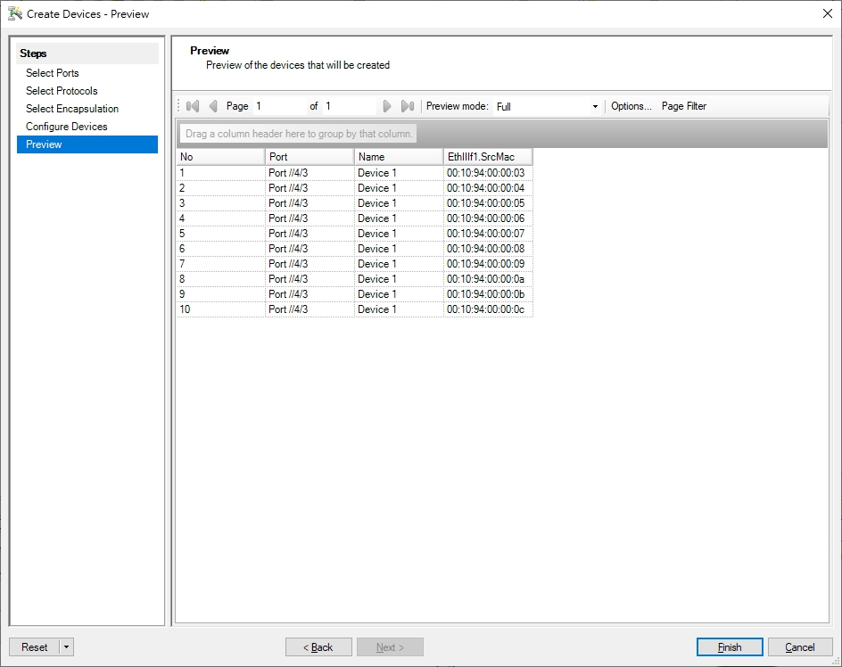
TestCenter Port 4/3
- Simulate 10 clients.
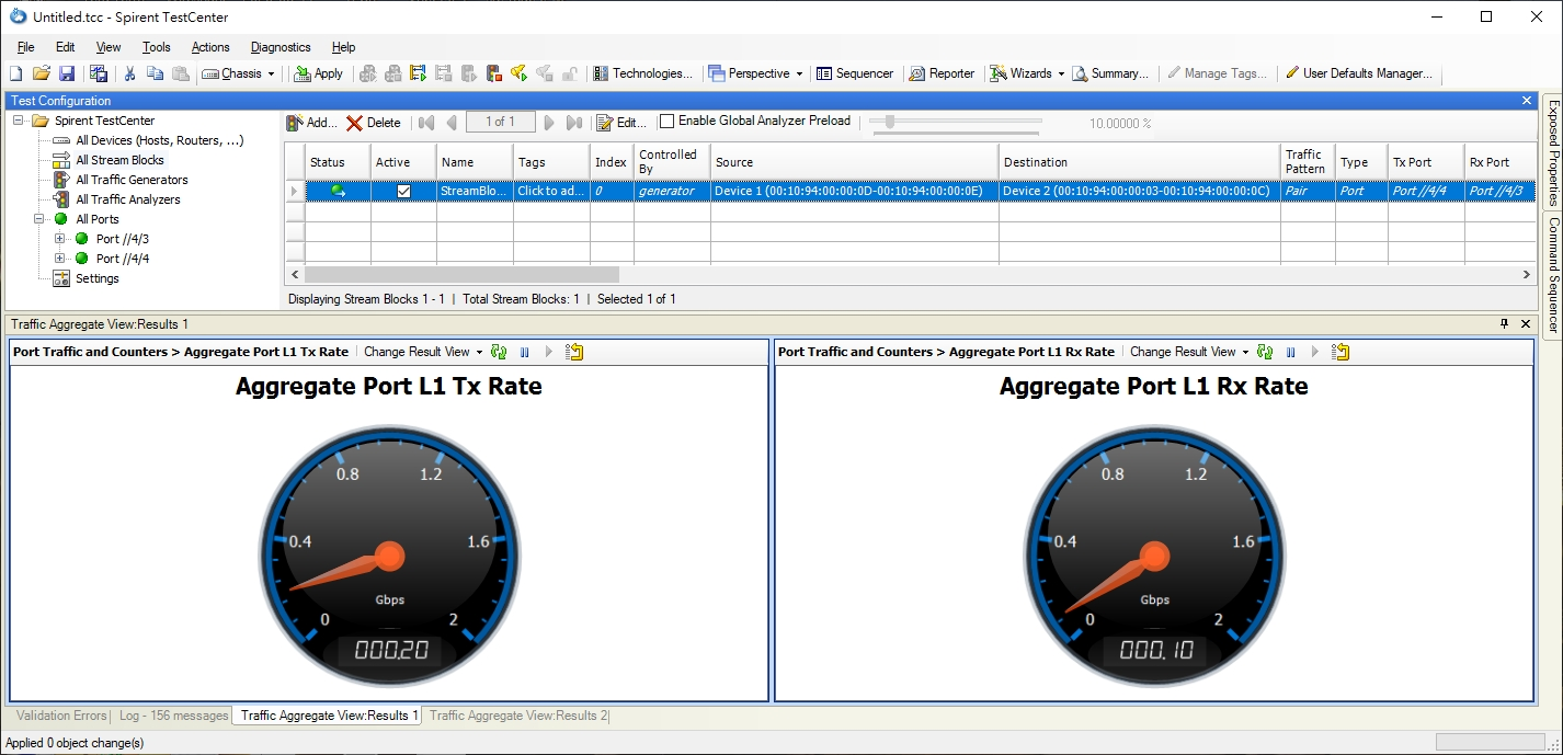
- Test default configuration “src-dst-mac”
- The packet flow is concentrated in one port, load balance result did not meet expectations. (TX: 200 Mbps; RX: 100 Mbps)
- Modify load balance configuration to “src-mac”
- The packet flow is distributed in two ports, load balance appear. (TX: 200 Mbps; RX: 200 Mbps)

Conclusion
The packet load balance depends on chip configuration, three bits (the LSBs) are used to index trunk table to choose one of port.
SIP and DIP criteria are used for IPv4 packets, for other packets the selection falls back to criteria based on the equivalent MAC address.
The usual way to do the load balance is “src-dst-mac”, so to test if the load balance is work, you must have a good SA or DA to XOR.
Of course in normal condition, we don’t have continuous MAC Address situation unless whole lot shipment. If load balance does not work well, you can try different hash to improve result as above experiment.
The article introduces ERPS with multiple instance.
(Click here for Basic ERPS configuration (single ring) with multiple instance.)
Support models and software version:
ECS4120 Series V1.2.2.18 and above.
ECS4100 Series V1.2.36.191 and above.
Overview
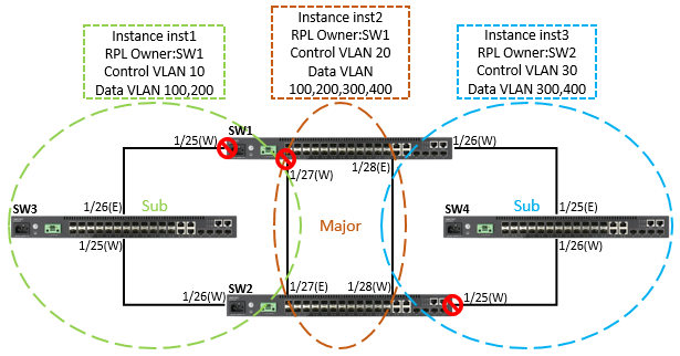
ERPS Version 2 supports multiple rings and ladder topology.
ERPS control packets can only be sent on one instance. The secondary(sub) ring needs to specify the major instance which will be used to send ERPS control packets.
In the multi-ring/ladder network scenario, a failure on a ring link between interconnection nodes of a sub-ring triggers the actions only on the Ethernet ring that the sub-ring is attached to. On the other hand, other ring link failures trigger the actions within the Ethernet ring that the failed ring link belongs to.
Topology
Configuration
SW1
SW1#configure
SW1(config)#interface ethernet 1/25
SW1(config-if)#switchport allowed vlan add 10,100,200 tagged
SW1(config-if)#spanning-tree spanning-disabled
SW1(config-if)#exit
SW1(config)#interface ethernet 1/26
SW1(config-if)#switchport allowed vlan add 30,300,400 tagged
SW1(config-if)#spanning-tree spanning-disabled
SW1(config-if)#exit
SW1(config)#interface ethernet 1/27
SW1(config-if)#switchport allowed vlan add 10,20,30,100,200,300,400 tagged
SW1(config-if)#spanning-tree spanning-disabled
SW1(config-if)#exit
SW1(config)#interface ethernet 1/28
SW1(config-if)#switchport allowed vlan add 10,20,30,100,200,300,400 tagged
SW1(config-if)#spanning-tree spanning-disabled
SW1(config-if)#exit
SW1(config)#erps
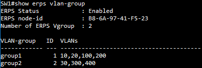
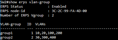
SW1(config)#erps vlan-group group1 add 10,20,100,200
SW1(config)#erps vlan-group group2 add 30,300,400
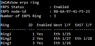
SW1(config)#erps ring Ring1
SW1(config-erps-ring)#ring-port west interface ethernet 1/25
SW1(config-erps-ring)#enable
SW1(config-erps-ring)#exit
SW1(config)#erps ring Ring2
SW1(config-erps-ring)#ring-port west interface ethernet 1/27
SW1(config-erps-ring)#ring-port east interface ethernet 1/28
SW1(config-erps-ring)#enable
SW1(config-erps-ring)#exit
SW1(config)#erps ring Ring3
SW1(config-erps-ring)#ring-port west interface ethernet 1/26
SW1(config-erps-ring)#enable
SW1(config-erps-ring)#exit
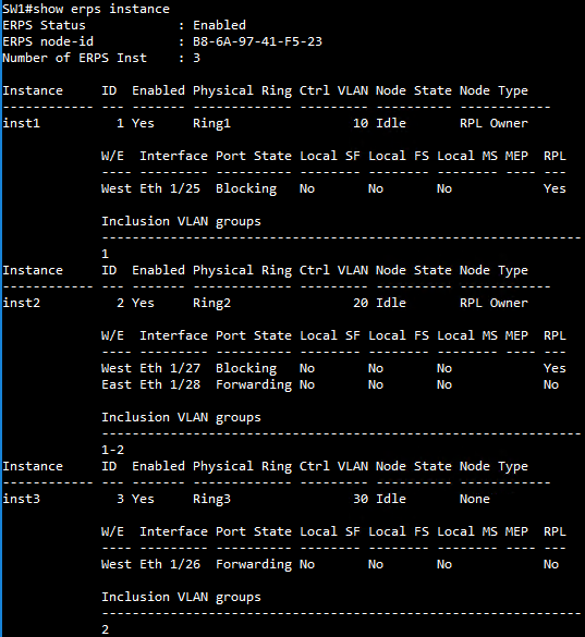
SW1(config)#erps instance inst2 id 2
SW1(config-erps-inst)#control-vlan 20
SW1(config-erps-inst)#rpl owner
SW1(config-erps-inst)#physical-ring Ring2
SW1(config-erps-inst)#inclusion-vlan group1
SW1(config-erps-inst)#inclusion-vlan group2
SW1(config-erps-inst)#enable
SW1(config-erps-inst)#exit
SW1(config)#erps instance inst1 id 1
SW1(config-erps-inst)#control-vlan 10
SW1(config-erps-inst)#rpl owner
SW1(config-erps-inst)#physical-ring Ring1
SW1(config-erps-inst)#major-ring inst2
SW1(config-erps-inst)#inclusion-vlan group1
SW1(config-erps-inst)#enable
SW1(config-erps-inst)#exit
SW1(config)#erps instance inst3 id 3
SW1(config-erps-inst)#control-vlan 30
SW1(config-erps-inst)#physical-ring Ring3
SW1(config-erps-inst)#major-ring inst2
SW1(config-erps-inst)#inclusion-vlan group2
SW1(config-erps-inst)#enable
SW1(config-erps-inst)#end
SW2
SW2#configure
SW2(config)#interface ethernet 1/25
SW2(config-if)#switchport allowed vlan add 30,300,400 tagged
SW2(config-if)#spanning-tree spanning-disabled
SW2(config-if)#exit
SW2(config)#interface ethernet 1/26
SW2(config-if)#switchport allowed vlan add 10,100,200 tagged
SW2(config-if)#spanning-tree spanning-disabled
SW2(config-if)#exit
SW2(config)#interface ethernet 1/27
SW2(config-if)#switchport allowed vlan add 10,20,30,100,200,300,400 tagged
SW2(config-if)#spanning-tree spanning-disabled
SW2(config-if)#exit
SW2(config)#interface ethernet 1/28
SW2(config-if)#switchport allowed vlan add 10,20,30,100,200,300,400 tagged
SW2(config-if)#spanning-tree spanning-disabled
SW2(config-if)#exit
SW2(config)#erps
SW2(config)#erps vlan-group group1 add 10,20,100,200
SW2(config)#erps vlan-group group2 add 30,300,400
SW2(config)#erps ring Ring1
SW2(config-erps-ring)#ring-port west interface ethernet 1/26
SW2(config-erps-ring)#enable
SW2(config-erps-ring)#exit
SW2(config)#erps ring Ring2
SW2(config-erps-ring)#ring-port west interface ethernet 1/28
SW2(config-erps-ring)#ring-port east interface ethernet 1/27
SW2(config-erps-ring)#enable
SW2(config-erps-ring)#exit
SW2(config)#erps ring Ring3
SW2(config-erps-ring)#ring-port west interface ethernet 1/25
SW2(config-erps-ring)#enable
SW2(config-erps-ring)#exit
SW2(config)#erps instance inst2 id 2
SW2(config-erps-inst)#control-vlan 20
SW2(config-erps-inst)#physical-ring Ring2
SW2(config-erps-inst)#inclusion-vlan group1
SW2(config-erps-inst)#inclusion-vlan group2
SW2(config-erps-inst)#enable
SW2(config-erps-inst)#exit
SW2(config)#erps instance inst1 id 1
SW2(config-erps-inst)#control-vlan 10
SW2(config-erps-inst)#physical-ring Ring1
SW2(config-erps-inst)#major-ring inst2
SW2(config-erps-inst)#inclusion-vlan group1
SW2(config-erps-inst)#enable
SW2(config-erps-inst)#exit
SW2(config)#erps instance inst3 id 3
SW2(config-erps-inst)#control-vlan 30
SW2(config-erps-inst)#rpl owner
SW2(config-erps-inst)#physical-ring Ring3
SW2(config-erps-inst)#major-ring inst2
SW2(config-erps-inst)#inclusion-vlan group2
SW2(config-erps-inst)#enable
SW2(config-erps-inst)#end
SW3
SW3#configure
SW3(config)#interface ethernet 1/25
SW3(config-if)#switchport allowed vlan add 10,100,200 tagged
SW3(config-if)#spanning-tree spanning-disabled
SW3(config-if)#exit
SW3(config)#interface ethernet 1/26
SW3(config-if)#switchport allowed vlan add 10,100,200 tagged
SW3(config-if)#spanning-tree spanning-disabled
SW3(config-if)#exit
SW3(config)#erps
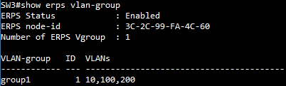
SW3(config)#erps vlan-group group1 add 10,100,200
SW3(config)#erps ring Ring1
SW3(config-erps-ring)#ring-port west interface ethernet 1/25
SW3(config-erps-ring)#ring-port east interface ethernet 1/26
SW3(config-erps-ring)#enable
SW3(config-erps-ring)#exit
SW3(config)#erps instance inst1 id 1
SW3(config-erps-inst)#control-vlan 10
SW3(config-erps-inst)#physical-ring Ring1
SW3(config-erps-inst)#inclusion-vlan group1
SW3(config-erps-inst)#enable
SW3(config-erps-inst)#end
SW4
SW4#configure
SW4(config)#interface ethernet 1/25
SW4(config-if)#switchport allowed vlan add 30,300,400 tagged
SW4(config-if)#spanning-tree spanning-disabled
SW4(config-if)#exit
SW4(config)#interface ethernet 1/26
SW4(config-if)#switchport allowed vlan add 30,300,400 tagged
SW4(config-if)#spanning-tree spanning-disabled
SW4(config-if)#exit
SW4(config)#erps
SW4(config)#erps vlan-group group2 add 30,300,400
SW4(config)#erps ring Ring3
SW4(config-erps-ring)#ring-port west interface ethernet 1/26
SW4(config-erps-ring)#ring-port east interface ethernet 1/25
SW4(config-erps-ring)#enable
SW4(config-erps-ring)#exit
SW4(config)#erps instance inst3 id 1
SW4(config-erps-inst)#control-vlan 30
SW4(config-erps-inst)#physical-ring Ring3
SW4(config-erps-inst)#inclusion-vlan group2
SW4(config-erps-inst)#enable
SW4(config-erps-inst)#end
SW1 VLAN group configuration
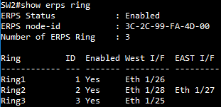
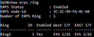
SW1 ERPS ring configuration
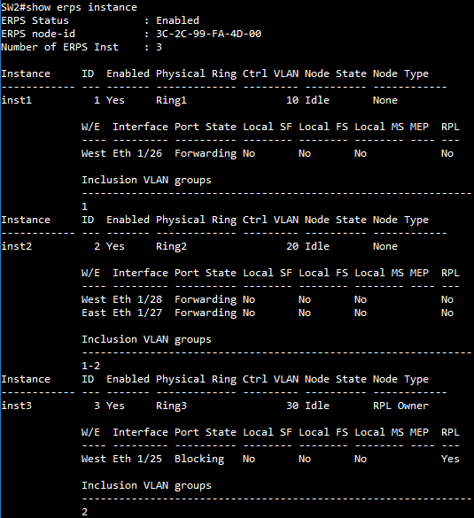
SW1 ERPS instance configuration
SW2 VLAN group configuration
SW2 ERPS ring configuration
SW2 ERPS instance configuration
SW3 VLAN group configuration
SW3 ERPS ring configuration
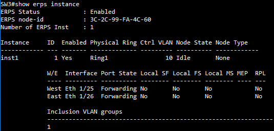
SW3 ERPS instance configuration
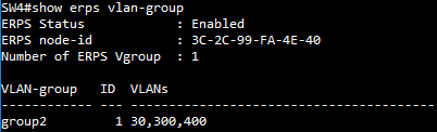
SW4 VLAN group configuration
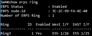
SW4 ERPS ring configuration
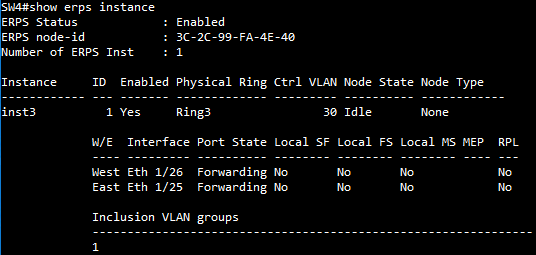
SW4 ERPS instance configuration
Ports can be statically grouped into an aggregate link (i.e., trunk) to increase the bandwidth of a network connection or to ensure fault recovery. Or you can use the Link Aggregation Control Protocol (LACP) to automatically negotiate a trunk link between this switch and another network device.
Support Models: ECS4620 series, ECS4510 series, ECS4120 series, ECS4100 series, ECS5520 series, ECS4530 series, ECS2100 series, ECS2110 series, ECS3510 series
How to create Link Aggregation/Port-Channel on the switch ?
We have two methods to group the ports into an aggregate link, please refer to the following comparison table.
| Link Aggregation/Port-Channel | |
| Dynamic Mode | Manual Mode |
| Link Aggregation Control Protocol (LACP) | Static Trunk |
| LACP will automatically be assigned the next available port-channel ID. | Users have to create port-channel ID manually first. |
| Console(config)#interface ethernet 1/x Console(config-if)#lacp |
Console(config)#interface ethernet 1/x Console(config-if)#channel-group channel-id |
| *** Please note that LACP and static trunk can't be used together on the same interface.*** | |
Topology:
1. Link Aggregation Control Protocol (LACP)
The configuration on the SW1 and SW2:
Console#configure
Console(config)#interface ethernet 1/1,2
Console(config-if)#lacp
Console(config-if)#end
The status of Port-channel:
Console#show interfaces status port-channel 1
Information of Trunk 1
 Basic Information:
 Port Type : 1000BASE-T
 MAC Address : 04-F8-F8-5C-2D-23
 Configuration:
 Name :
 Port Admin : Up
 Speed-duplex : Auto
 Capabilities : 10half, 10full, 100half, 100full, 1000full
 Broadcast Storm : Disabled
 Broadcast Storm Limit : 500 packets/second
 Multicast Storm : Disabled
 Multicast Storm Limit : 500 packets/second
 Unknown Unicast Storm : Disabled
 Unknown Unicast Storm Limit : 500 packets/second
 Storm Threshold Resolution : 1 packets/second
 Flow Control : Disabled
 VLAN Trunking : Disabled
 MAC Learning : Enabled
 Link-up-down Trap : Enabled
 Current Status:
 Created By : LACP
 Link Status : Up
 Port Operation Status : Up
 Operation Speed-duplex : 1000full
 Up Time : 0w 0d 0h 3m 37s (217 seconds)
 Flow Control Type : None
 Max Frame Size : 1518 bytes (1522 bytes for tagged frames)
 MAC Learning Status : Enabled
 Member Ports : Eth1/1, Eth1/2
 Active Member Ports : Eth1/1, Eth1/2
If you want to assign the LACP trunk link to the specific port-channel number, you need to use the admin-key.
Please refer to the FAQ: How to use admin-key to assign port-channel number ?
2. Static Trunk
The configuration on the SW1 and SW2:
Console#configure
Console(config)#interface port-channel 1
Console(config-if)#exit
Console(config)#interface ethernet 1/1,2
Console(config-if)#channel-group 1
Console(config-if)#end
The status of Port-channel:
Console#show interfaces status port-channel 1
Information of Trunk 1
 Basic Information:
 Port Type : 1000BASE-T
 MAC Address : 04-F8-F8-5C-2D-23
 Configuration:
 Name :
 Port Admin : Up
 Speed-duplex : Auto
 Capabilities : 10half, 10full, 100half, 100full, 1000full
 Broadcast Storm : Disabled
 Broadcast Storm Limit : 500 packets/second
 Multicast Storm : Disabled
 Multicast Storm Limit : 500 packets/second
 Unknown Unicast Storm : Disabled
 Unknown Unicast Storm Limit : 500 packets/second
 Storm Threshold Resolution : 1 packets/second
 Flow Control : Disabled
 VLAN Trunking : Disabled
 MAC Learning : Enabled
 Link-up-down Trap : Enabled
 Current Status:
 Created By : User
 Link Status : Up
 Port Operation Status : Up
 Operation Speed-duplex : 1000full
 Up Time : 0w 0d 0h 0m 41s (41 seconds)
 Flow Control Type : None
 Max Frame Size : 1518 bytes (1522 bytes for tagged frames)
 MAC Learning Status : Enabled
 Member Ports : Eth1/1, Eth1/2
 Active Member Ports : Eth1/1, Eth1/2
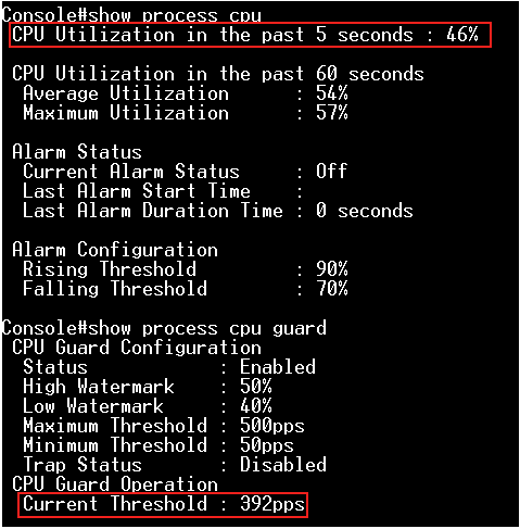
According to the current CPU utilization, CPU guard function sets the CPU utilization high and low watermarks in the percentage of CPU time utilized, and the CPU high and low thresholds in the number of packets being processed per second.
** Please note that the CPU guard will limit the packets transfer to CPU, but it will not limit the packets transmit to the egress port. **
Support Models: ECS4620 series, ECS4510 series, ECS4120 series, ECS4100 series, ECS5520 series, ECS4530 series, ECS2100 series, ECS3510 series
Topology:

Step 1: The switch runs in the default configuration and we try to inject the 1000 packets per second.
The CPU utilization will rise to 55 ~ 58%.
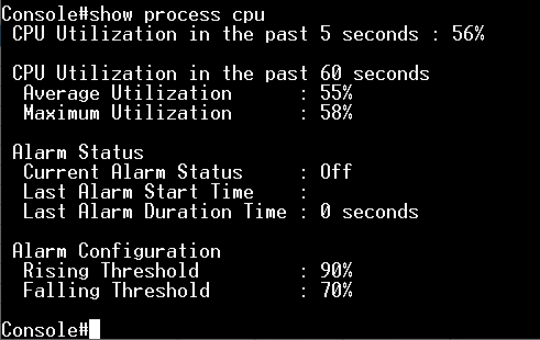
Step 2: Enable the CPU guard function globally.
Console(config)#process cpu guard
At this moment, the CPU remains and doesn't fall.
Since the current CPU utilization does not exceed the value of high-watermark, it doesn't trigger the CPU guard.
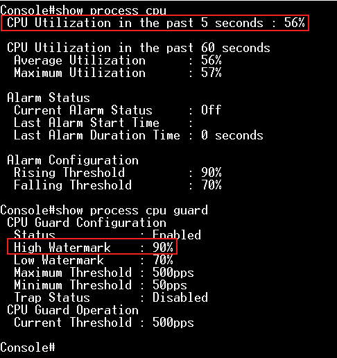
Step 3: Modify "low-watermark" and "high-watermark".
For example, we configure "high-watermark" to be lower than the current CPU utilization.
Console(config)#process cpu guard low-watermark 40
Console(config)#process cpu guard high-watermark 50
After the modification, CPU utilization will be falling and the CPU can process 392 packets per second.
It's because the current CPU utilization is higher than the high-watermark, the switch limits the packets flow to the CPU until it falls below the low-watermark.
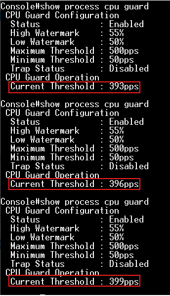
Step 4: Modify "low-watermark" and "high-watermark".
For example, we configure "low-watermark" to be higher than the current CPU utilization.
Console(config)#process cpu guard low-watermark 50
Console(config)#process cpu guard high-watermark 55
We can see the "Current Threshold" is increasing, and the maximum value is 500 (ECS4510 Series).
If the switch limits the packets flow to the CPU after exceeding the high-watermark, the normal flow will be restored after usage falls beneath the low-watermark.
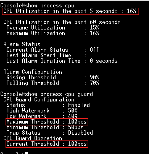
Step 5: We can also modify the "Maximum Threshold" directly to specify the number of packets being processed per second by the CPU.
Console(config)#process cpu guard max-threshold 100
The ECS5520-18X has sixteen 10G SFP+ ports and two 40G QSFP+ uplink ports. The 10G/40G ports can be configured as a single port connected with 10G SFP+/40G QSFP+ fiber cable, 10G/40G DAC (direct attach) cable, or breakout cable that connects a 40G port to four 10G ports; 10G port can also group four ports to a single 40G port. It's flexible for the user to configure it.
Configuration (Support CLI/WEB GUI/SNMP)
This example shows the default 40G and 10G port settings on ECS5520-18X.
Console#show hardware profile portmode
40G         10G         Config  Oper
Interfaces  Interfaces  Mode    Mode
----------  ----------  ------  ------
1/1         1/1-4       -       4x10g
1/5         1/5-8       -       4x10g
1/9         1/9-12      -       4x10g
1/13        1/13-16     -       4x10g
1/17        1/19-22     -       1x40g
1/18        1/23-26     -       1x40g
<A> CLI Command
- Configure port settings for 1x40G or 4x10G operation.
[CLI format]
hardware profile portmode ethernet 1/port { 1x40g | 4x10g | reset }
Warning: This command will not take effect until reload.
1x40g - Configures the port as a single 40G port.
4x10g - Configures the port as four 10G ports.
reset - Configures port mode to the default setting.
<A-1> Group four 10G ports to a single 40G port.
Eth1/1-4 will group to a single 40G port (Eth1/1).
Console#hardware profile portmode ethernet 1/1 1x40g
Warning: This command will not take effect until reload.
Console#reload
System will be restarted. Continue <y/n>? y
Console#show hardware profile portmode
40G         10G         Config  Oper
Interfaces  Interfaces  Mode    Mode
----------  ----------  ------  ------
1/1         1/1-4       1x40g   1x40g
1/5         1/5-8       -       4x10g
1/9         1/9-12      -       4x10g
1/13        1/13-16     -       4x10g
1/17        1/19-22     -       1x40g
1/18        1/23-26     -       1x40g
Console#show interfaces brief
Interface Name              Status    PVID Pri Speed/Duplex  Type         Trunk
--------- ----------------- --------- ---- --- ------------- ------------ -----
Eth 1/ 1                    Up           1   0 40Gfull       40GBASE QSFP None
Eth 1/ 5                    Down         1   0 10Gfull       10GBASE SFP+ None
Eth 1/ 6                    Down         1   0 10Gfull       10GBASE SFP+ None
<A-2> Breakout a single 40G port to four 10G ports.
Eth1/17 will breakout to four 10G ports (Eth1/19-22).
Console#hardware profile portmode ethernet 1/17 4x10g
Warning: This command will not take effect until reload.
Console#reload
System will be restarted. Continue <y/n>? y
Console#show hardware profile portmode
40G         10G         Config  Oper
Interfaces  Interfaces  Mode    Mode
----------  ----------  ------  ------
1/1         1/1-4       -       4x10g
1/5         1/5-8       -       4x10g
1/9         1/9-12      -       4x10g
1/13        1/13-16     -       4x10g
1/17        1/19-22     4x10g   4x10g
1/18        1/23-26     -       1x40g
Console#show interfaces brief
Interface Name              Status    PVID Pri Speed/Duplex  Type         Trunk
--------- ----------------- --------- ---- --- ------------- ------------ -----
...Omit
Eth 1/16                    Down         1   0 10Gfull       10GBASE SFP+ None
Eth 1/18                    Down         1   0 40Gfull       40GBASE QSFP None
Eth 1/19                    Up           1   0 10Gfull       10GBASE SFP+ None
Eth 1/20                    Up           1   0 10Gfull       10GBASE SFP+ None
Eth 1/21                    Up           1   0 10Gfull       10GBASE SFP+ None
Eth 1/22                    Up           1   0 10Gfull       10GBASE SFP+ None
<A-3> Configure port mode to the default setting.
Console#hardware profile portmode ethernet 1/1 reset
Warning: This command will not take effect until reload.
Console#hardware profile portmode ethernet 1/17 reset
Warning: This command will not take effect until reload.
Console#reload
System will be restarted. Continue <y/n>? y
Console#show hardware profile portmode
40G         10G         Config  Oper
Interfaces  Interfaces  Mode    Mode
----------  ----------  ------  ------
1/1         1/1-4       -       4x10g
1/5         1/5-8       -       4x10g
1/9         1/9-12      -       4x10g
1/13        1/13-16     -       4x10g
1/17        1/19-22     -       1x40g
1/18        1/23-26     -       1x40g
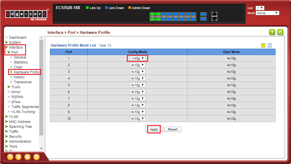
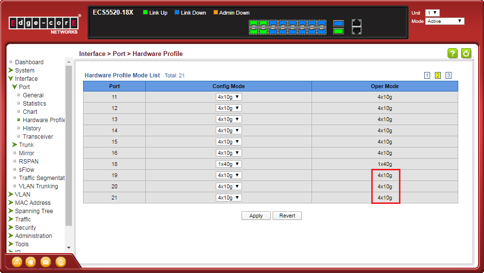
<B> WEB GUI
- Configure port settings for 1x40G or 4x10G operation.
[WEB GUI]
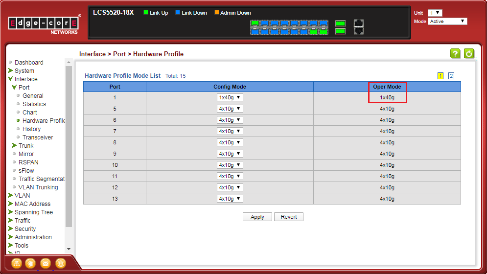
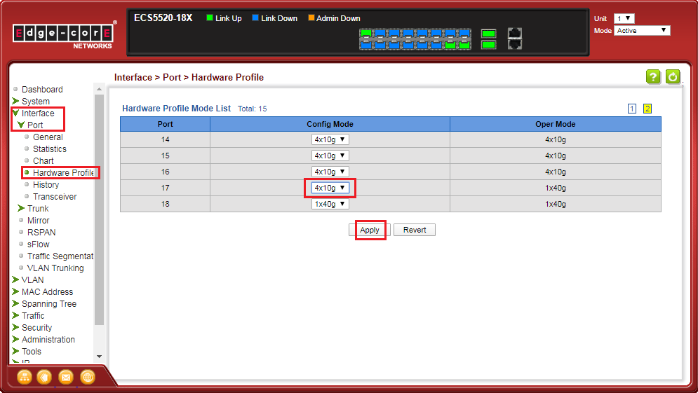
Interface -> Port -> Hardware Profile -> Config Mode -> Apply
<B-1> Group four 10G ports to a single 40G port.
Eth1/1-4 will group to a single 40G port (Eth1/1).
<B-2> Breakout a single 40G port to four 10G ports.
Eth1/17 will breakout to four 10G ports (Eth1/19-22).
<C> SNMP
- Configure port settings for 1x40G or 4x10G operation.
[SNMPSET command format]
snmpwalk -v 2c -c private {switch ip} {hardwarePortModeOper}.{hardwarePortModeIfIndex}snmpset -v 2c -c private {switch ip} {hardwarePortModeConfig}.{hardwarePortModeIfIndex} {integer} {value}
For hardwarePortModeOper, OID 1.3.6.1.4.1.259.10.1.51.1.2.16.1.1.2
The Hardware profile operational port mode. This setting is used to identify the active state of port mode.
The value mode4x10g(2) means the port operates a single 10G port.
The value mode1x40g(3) means the port operates a single 40G port.
For hardwarePortModeConfig, OID 1.3.6.1.4.1.259.10.1.51.1.2.16.1.1.3
This is used to configure hardware profile port mode settings. This action will reflect after the restart.
Set mode4x10g(2) to breakout a single 40G port to four 10G ports.
Set mode1x40g(3) to group four 10G ports to a single 40G port.
For hardwarePortModeIfIndex: The port interface of hardwarePortModeIfIndex.
The ifIndex value of the port or trunk.
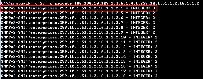
<C-1> Group four 10G ports to a single 40G port.
C:\>snmpwalk -v 2c -c private 188.188.10.109 1.3.6.1.4.1.259.10.1.51.1.2.16.1.1.2.1
SNMPv2-SMI::enterprises.259.10.1.51.1.2.16.1.1.2.1 = INTEGER: 2

C:\>snmpset -v 2c -c private 188.188.10.109 1.3.6.1.4.1.259.10.1.51.1.2.16.1.1.3.1 i 3
SNMPv2-SMI::enterprises.259.10.1.51.1.2.16.1.1.3.1 = INTEGER: 3

Eth1/1-4 will group to a single 40G port (Eth1/1).
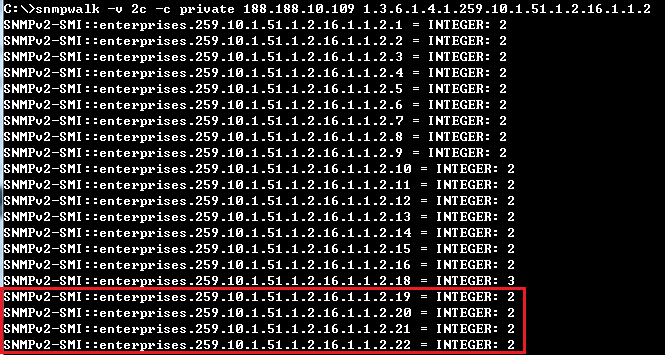
<C-2> Breakout a single 40G port to four 10G ports.
C:\>snmpwalk -v 2c -c private 188.188.10.109 1.3.6.1.4.1.259.10.1.51.1.2.16.1.1.2.17
SNMPv2-SMI::enterprises.259.10.1.51.1.2.16.1.1.2.17 = INTEGER: 3

C:\>snmpset -v 2c -c private 188.188.10.109 1.3.6.1.4.1.259.10.1.51.1.2.16.1.1.3.17 i 2
SNMPv2-SMI::enterprises.259.10.1.51.1.2.16.1.1.3.17 = INTEGER: 2

Eth1/17 will breakout to four 10G ports (Eth1/19-22).
- Enable the basic DHCPSNP function.
Console#con
Console(config)#ip dhcp snooping
Console(config)#ip dhcp snooping vlan 1
Console(config)#interface ethernet 1/28
Console(config-if)#ip dhcp snooping trust
Console(config-if)#end
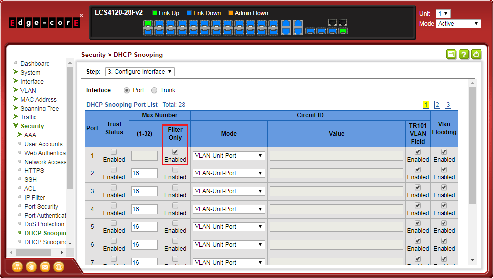
- Enable DHCPSNP filter-only mode on port interface configuration.
ip dhcp snooping max-number { <max_num> | filter-only }
Console#con
Console(config)#interface ethernet 1/1
Console(config-if)#ip dhcp snooping max-number filter-only
Console(config-if)#end
Console#show ip dhcp snooping
Global DHCP Snooping Status: enabled
DHCP Snooping Information Option Status: disabled
DHCP Snooping Information Option Sub-option Format: extra subtype included
DHCP Snooping Information Option Remote ID: MAC Address (hex encoded)
DHCP Snooping Information Option Remote ID TR101 VLAN Field: enabled
DHCP Snooping Information Option TR101 Board ID: none
DHCP Snooping Information Policy: replace
DHCP Snooping is configured on the following VLANs:
   1
Verify Source MAC-Address: enabled
DHCP Snooping Rate Limit: unlimited
                  Max  Circuit-ID      Circuit-ID  Circuit-ID Carry To  Vlan
Interface Trusted Num  mode            Value       TR101 VLAN Client    Flooding
--------- ------- ---- --------------- ----------- ---------- --------  --------
Eth 1/1   No      filter-only  VLAN-Unit-Port  --- enabled    disabled  enabled
Eth 1/2   No      16   VLAN-Unit-Port  ---         enabled    disabled  enabled
Eth 1/3   No      16   VLAN-Unit-Port  ---         enabled    disabled  enabled
- Enable DHCPSNP filter-only mode on port interface configuration.
- Enable DHCPSNP filter-only mode on port interface configuration.
snmpset -v 2c -c private {switch ip} {dhcpSnoopPortMaxNumber}.{dhcpSnoopPortIfIndex} {integer} {value}
C:\>snmpset -v 2c -c private 192.168.1.2 1.3.6.1.4.1.259.10.1.45.1.46.3.1.1.6.2 i 65535
SNMPv2-SMI::enterprises.259.10.1.45.1.46.3.1.1.6.2 = INTEGER: 65535

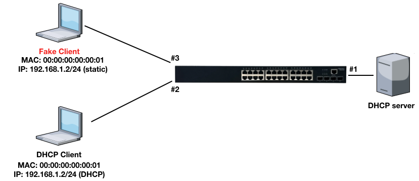
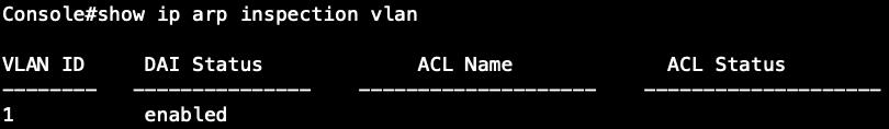
Dynamic ARP Inspection(DAI) is a security feature that validates the MAC Address bindings for Address Resolution Protocol packets. It provides protection against ARP traffic with invalid MAC-to-IP address bindings. This is accomplished by intercepting all ARP requests and responses and verifying each of these packets before the local ARP cache is updated or the packet is forwarded to the appropriate destination, dropping any invalid ARP packets.
ARP Inspection determines the validity of an ARP packet based on valid IP-to-MAC address bindings stored in a trusted database – the DHCP snooping binding database or IP source guard binding database. ARP Inspection can also validate ARP packets against user-configured ARP access control lists (ACLs) for hosts with statically configured IP addresses.
Topology:
Basic Configuration via CLI command:
Step 1: Enable the DHCPSNP function on global and VLAN 1.
Console(config)#ip dhcp snooping
Console(config)#ip dhcp snooping vlan 1
Step 2: Enable the DHCPSNP trust port on port 1.
Console(config)#interface ethernet 1/1
Console(config-if)#ip dhcp snooping trust
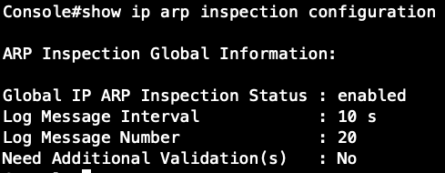
Step 3: Enable the DAI function on global and VLAN 1.
Console(config)#ip arp inspection
Console(config)#ip arp inspection vlan 1
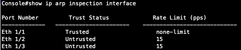
Console(config)#interface ethernet 1/1
Console(config-if)#ip arp inspection trust
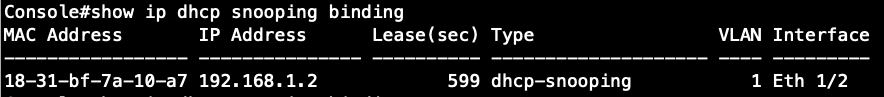
Step 4: DHCP client gets the IP address from the DHCP server.
Step 5: The fake client sets the same IP address as the DHCP client and tries to send the ARP request packet.
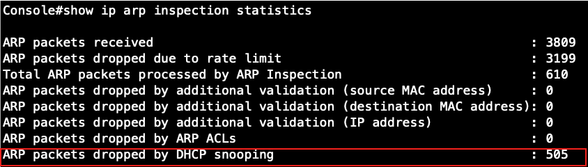
Result: The switch will drop the ARP packet from the fake client.
Basic Configuration via SNMP:
[SNMPSET command format]
snmpset -v 2c -c private {switch ip} {daiGlobalStatus | daiVlanStatus | daiPortTrustStatus}.{daiVlanIndex | daiPortIfIndex} {integer} {value}
For daiGlobalStatus, OID 1.3.6.1.4.1.259.10.1.45.1.56.1.1
Set enabled(1) to enable dynamic ARP inspection globally.
Set disabled(2) to disable dynamic ARP inspection globally.
For daiVlanStatus, OID 1.3.6.1.4.1.259.10.1.45.1.56.2.1.1.2
This object indicates whether dynamic ARP inspection is enabled in this VLAN.
Set enabled(1) to enable dynamic ARP inspection on VLAN.
Set disabled(2) to disable dynamic ARP inspection on VLAN.
For daiVlanIndex,
This object indicates the VLAN ID on which dynamic ARP inspection is configured.
For daiPortTrustStatus, OID 1.3.6.1.4.1.259.10.1.45.1.56.3.1.1.2
This object indicates whether the port is trusted for dynamic ARP inspection.
Set enabled(1) to enable dynamic ARP inspection trust port.
Set disabled(2) to disable dynamic ARP inspection trust port.
For daiPortIfIndex,
The ifIndex value of the port.
Step 1: Enable the DAI function globally.
root@gavin:~# snmpset -v 2c -c private 192.168.1.1 .1.3.6.1.4.1.259.10.1.45.1.56.1.1.0 i 1
Check the configuration on CLI and SNMP:
SNMP:

CLI:
Step 2: Enable the DAI function on VLAN 1. (daiVlanIndex=1)
root@gavin:~# snmpset -v 2c -c private 192.168.1.1 .1.3.6.1.4.1.259.10.1.45.1.56.2.1.1.2.1 i 1
Check the configuration on CLI and SNMP:
SNMP:

CLI:
Step 3: Enable the DAI trust port on Port 1. (daiPortIfIndex=1)
root@gavin:~# snmpset -v 2c -c private 192.168.1.1 .1.3.6.1.4.1.259.10.1.45.1.56.3.1.1.2.1 i 1
Check the configuration on CLI and SNMP:
SNMP:

CLI:
Open Shortest Path First (OSPF) is a routing protocol for Internet Protocol (IP) networks. It uses a link-state routing protocol to generate a shortest-path tree, then builds up its routing table based on this tree. OSPF produces a more stable network because the participating routers act on network changes predictably and simultaneously, converging on the best route more quickly than RIP. Moreover, when several equal-cost routes to a destination exist, traffic can be distributed equally among them. A separate routing area scheme is also used to further reduce the amount of routing traffic.
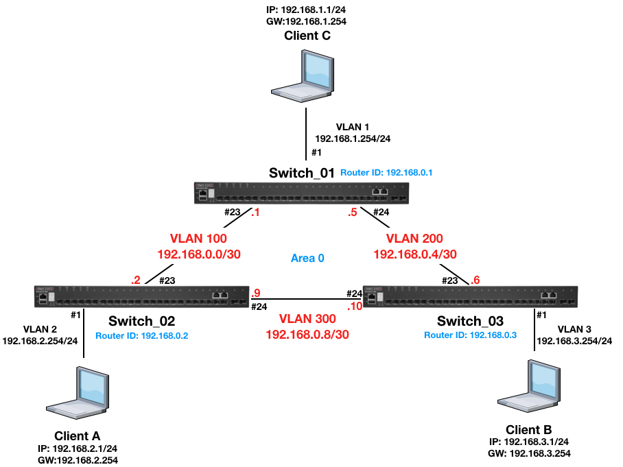
Topology:
Procedure:
Switch_01 Configuration:
Step 1: Apply VLAN on port and configure VLAN's IP address.
switch-01(config)#interface ethernet 1/23
switch-01(config-if)#switchport allowed vlan add 100
switch-01(config-if)#switchport native vlan 100
switch-01(config-if)#exit
switch-01(config)#interface ethernet 1/24
switch-01(config-if)#switchport allowed vlan add 200
switch-01(config-if)#switchport native vlan 200
switch-01(config-if)#exit
switch-01(config)#interface vlan 100
switch-01(config-if)#ip address 192.168.0.1/30
switch-01(config-if)#exit
switch-01(config)#interface vlan 200
switch-01(config-if)#ip address 192.168.0.5/30
switch-01(config-if)#exit
switch-01(config)#interface vlan 1
switch-01(config-if)#ip address 192.168.1.254/24
switch-01(config-if)#exit
Step 2: Disable spanning tree on port 23,24.
switch-01#con
switch-01(config)#interface ethernet 1/23,24
switch-01(config-if)#spanning-tree spanning-disabled
Step 3: Configure OSPF function.
switch-01(config)#router ospf 1
switch-01(config-router)#router-id 192.168.0.1
switch-01(config-router)#network 192.168.0.0 255.255.255.252 area 0
switch-01(config-router)#network 192.168.0.4 255.255.255.252 area 0
switch-01(config-router)#network 192.168.1.0 255.255.255.0 area 0
Switch_02 Configuration:
Step 1: Apply VLAN on port and configure VLAN's IP address.
switch-02(config)#interface ethernet 1/1
switch-02(config-if)#switchport native vlan 2
switch-02(config-if)#switchport allowed vlan add 2
switch-02(config-if)#exit
switch-02(config)#interface ethernet 1/23
switch-02(config-if)#switchport native vlan 100
switch-02(config-if)#switchport allowed vlan add 100
switch-02(config-if)#exit
switch-02(config)#interface ethernet 1/24
switch-02(config-if)#switchport native vlan 300
switch-02(config-if)#switchport allowed vlan add 300
switch-02(config-if)#exit
switch-02(config)#interface vlan 2
switch-02(config-if)#ip address 192.168.2.254/24
switch-02(config-if)#exit
switch-02(config)#interface vlan 100
switch-02(config-if)#ip address 192.168.0.2/30
switch-02(config-if)#exit
switch-02(config)#interface vlan 300
switch-02(config-if)#ip address 192.168.0.9/30
switch-02(config-if)#exit
Step 2: Disable spanning tree on port 23,24.
switch-01#con
switch-01(config)#interface ethernet 1/23,24
switch-01(config-if)#spanning-tree spanning-disabled
Step 3: Configure OSPF function.
switch-02(config)#router ospf 1
switch-02(config-router)#router-id 192.168.0.2
switch-02(config-router)#network 192.168.0.0 255.255.255.252 area 0
switch-02(config-router)#network 192.168.0.8 255.255.255.252 area 0
switch-02(config-router)#network 192.168.2.0 255.255.255.0 area 0
Switch_03 Configuration:
Step 1: Apply VLAN on port and configure VLAN's IP address.
switch-03(config)#interface ethernet 1/1
switch-03(config-if)#switchport native vlan 3
switch-03(config-if)#switchport allowed vlan add 3
switch-03(config-if)#exit
switch-03(config)#interface ethernet 1/23
switch-03(config-if)#switchport native vlan 200
switch-03(config-if)#switchport allowed vlan add 200
switch-03(config-if)#exit
switch-03(config)#interface ethernet 1/24
switch-03(config-if)#switchport native vlan 300
switch-03(config-if)#switchport allowed vlan add 300
switch-03(config-if)#exit
switch-03(config)#interface vlan 3
switch-03(config-if)#ip address 192.168.3.254/24
switch-03(config-if)#exit
switch-03(config)#interface vlan 200
switch-03(config-if)#ip address 192.168.0.6/30
switch-03(config-if)#exit
switch-03(config)#interface vlan 300
switch-03(config-if)#ip address 192.168.0.10/30
switch-03(config-if)#exit
Step 2: Disable spanning tree on port 23,24.
switch-01#con
switch-01(config)#interface ethernet 1/23,24
switch-01(config-if)#spanning-tree spanning-disabled
Step 3: Configure OSPF function.
switch-03(config)#router ospf 1
switch-03(config-router)#router-id 192.168.0.3
switch-03(config-router)#network 192.168.0.4 255.255.255.252 area 0
switch-03(config-router)#network 192.168.0.8 255.255.255.252 area 0
switch-03(config-router)#network 192.168.3.0 255.255.255.0 area 0
Result:
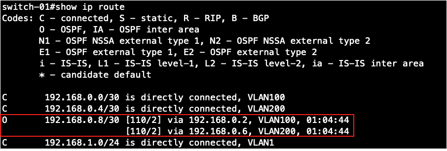
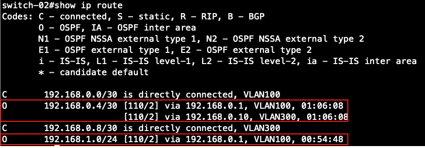
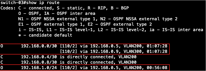
Check the routing table on all the switches.
Switch-01's routing table:
Switch-02's routing table:
Switch-03's routing table:
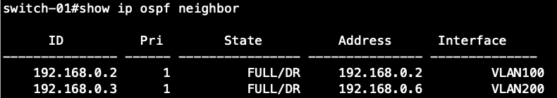
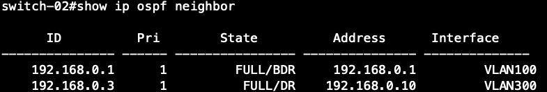
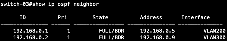
Display the information about neighboring routers on all the switches.
Switch-01's OSPF Neighbor Information
Switch-02's OSPF Neighbor Information
Switch-03's OSPF Neighbor Information
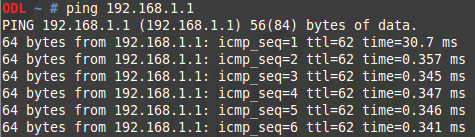
VLAN2-Client A(192.168.2.1) could ping to VLAN1-Client C(192.168.1.1).
Console#debug arp

Console#debug dhcp all


Console#debug igmpsnp-mvr all


Console# debug ip dhcp snooping all


Console#debug lacp config

Console#debug lacp event

Console#debug lacp packet

Console#debug mldsnp all


Console#debug mvr6 all


Console#debug spanning-tree all


Path Cost is used by the Spanning Tree Algorithm to determine the best path between devices. Therefore, lower values should be assigned to ports attached to faster media, and higher values assigned to ports with slower media.
By default, the system automatically detects the speed and duplex mode used on each port, and configures the path cost according to the values shown below.
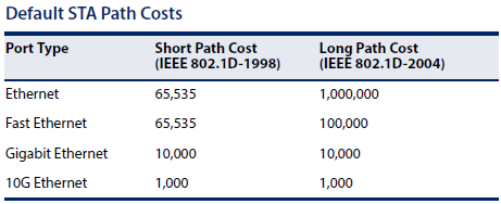
*The path cost of the STP is not configured by pathcost method short or long.
User can configure the spanning tree path cost for the specified interface by following command.
[CLI Command]
spanning-tree cost {cost}
cost - The path cost for the port.
(Range: 0 for auto-configuration, 1-65535 for short path cost method, 1-200,000,000 for long path cost method)
Calculate the spanning tree path cost on a port-channel.
1. Active Eth1/1 for port channel.
Console#show interfaces brief
Interface Name              Status    PVID Pri Speed/Duplex  Type         Trunk
--------- ----------------- --------- ---- --- ------------- ------------ -----
Eth 1/ 1                    Up           1   0 Auto-1000full 1000BASE-T   1
The spanning tree path cost on Trunk 1 is 5000.
Console#show spanning-tree brief
Interface Pri Designated            Designated Oper     STP    Role State Oper
              Bridge ID             Port ID    Cost     Status            Edge
--------- --- --------------------- ---------- -------- ------ ---- ----- ----
Trunk 1   128 32768.8CEA1B8AC667    128.57         5000 EN     ROOT FWD   No
The spanning tree path cost for Trunk 1 is 10000 (1G) / 2 = 5000 (Trunk).
The spanning tree path cost on Trunk 1 is 5000 (Trunk) / 1 = 5000.
2. Active Eth1/1 & Eth1/2 for port channel.
Console#show interfaces brief
Interface Name              Status    PVID Pri Speed/Duplex  Type         Trunk
--------- ----------------- --------- ---- --- ------------- ------------ -----
Eth 1/ 1                    Up           1   0 Auto-1000full 1000BASE-T   1
Eth 1/ 2                    Up           1   0 Auto-1000full 1000BASE-T   1
The spanning tree path cost on Trunk 1 is 2500.
Console#show spanning-tree brief
Interface Pri Designated            Designated Oper     STP    Role State Oper
              Bridge ID             Port ID    Cost     Status            Edge
--------- --- --------------------- ---------- -------- ------ ---- ----- ----
Trunk 1   128 32768.8CEA1B8AC667    128.57         2500 EN     ROOT FWD   No
The spanning tree path cost on Trunk 1 is 5000 (Trunk) / 2 = 2500.
3. Active Eth1/1 & Eth1/2 & Eth1/3 for port channel.
Console#show interfaces brief
Interface Name              Status    PVID Pri Speed/Duplex  Type         Trunk
--------- ----------------- --------- ---- --- ------------- ------------ -----
Eth 1/ 1                    Up           1   0 Auto-1000full 1000BASE-T   1
Eth 1/ 2                    Up           1   0 Auto-1000full 1000BASE-T   1
Eth 1/ 3                    Up           1   0 Auto-1000full 1000BASE-T   1
The spanning tree path cost on Trunk 1 is 1666.
Console#show spanning-tree brief
Interface Pri Designated            Designated Oper     STP    Role State Oper
              Bridge ID             Port ID    Cost     Status            Edge
--------- --- --------------------- ---------- -------- ------ ---- ----- ----
Trunk 1   128 32768.8CEA1B8AC667    128.57         1666 EN     ROOT FWD   No
The spanning tree path cost on Trunk 1 is 5000 (Trunk) / 3 = 1666.
4. Active Eth1/1 & Eth1/2 & Eth1/3 & Eth1/4 for port channel.
Console#show interfaces brief
Interface Name              Status    PVID Pri Speed/Duplex  Type         Trunk
--------- ----------------- --------- ---- --- ------------- ------------ -----
Eth 1/ 1                    Up           1   0 Auto-1000full 1000BASE-T   1
Eth 1/ 2                    Up           1   0 Auto-1000full 1000BASE-T   1
Eth 1/ 3                    Up           1   0 Auto-1000full 1000BASE-T   1
Eth 1/ 4                    Up           1   0 Auto-1000full 1000BASE-T   1
The spanning tree path cost on Trunk 1 is 1250.
Console#show spanning-tree brief
Interface Pri Designated            Designated Oper     STP    Role State Oper
              Bridge ID             Port ID    Cost     Status            Edge
--------- --- --------------------- ---------- -------- ------ ---- ----- ----
Trunk 1   128 32768.8CEA1B8AC667    128.57         1250 EN     ROOT FWD   No
The spanning tree path cost on Trunk 1 is 5000 (Trunk) / 4 = 1250.
The switch can display diagnostic information for SFP modules which support the SFF-8472 Specification for Diagnostic Monitoring Interface for Optical Transceivers. This information allows administrators to remotely diagnose problems with optical devices. This feature, referred to as Digital Diagnostic Monitoring (DDM) in the command display, provides information on transceiver parameters including temperature, supply voltage, laser bias current, laser power, received optical power, and related alarm thresholds.
transceiver-monitor
The setting for transceiver-monitor:
Console(config)#interface ethernet 1/X
Console(config-if)#transceiver-monitor
Use this command "transceiver-monitor" can monitor the current transceiver status, such as Temperature, TX power, RX power.
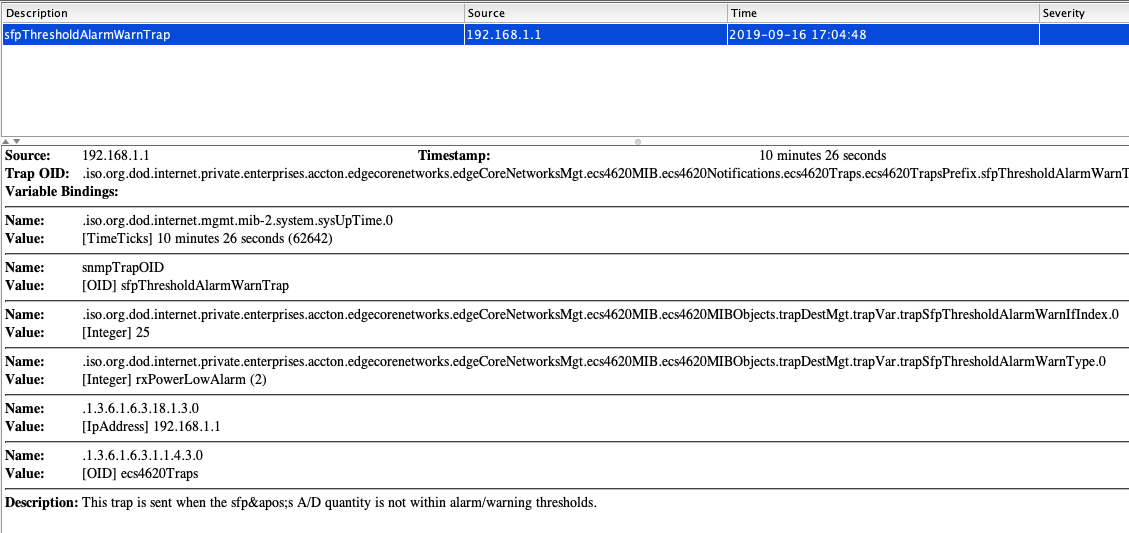
When any of the transceiver's operational values fall outside of specified thresholds, the switch will send the trap.
transceiver-threshold
The setting for transceiver-threshold:
Console(config)#interface ethernet 1/X
Console(config-if)#transceiver-threshold { current | rx-power | temperature | tx-power | voltage }
Use this command "transceiver-threshold" can set the default threshold from the transceiver to determine when an alarm or warning message should be sent.
Support Models: ECS4620 series, ECS4510 series, ECS4120 series, ECS4100 series, ECS2100 series, ECS2110 series
Topology:
Insert the transceiver --- (25)ECS4620-28T(1) --- SNMP server
The procedure to monitor the transceiver status :
Step 1: Configure the switch's IP address and enable the SNMP trap.
Console#con
Console(config)#interface vlan 1
Console(config-if)#ip address 192.168.1.1/24
Console(config-if)#exit
Console(config)#snmp-server host 192.168.1.100 inform private version 2c
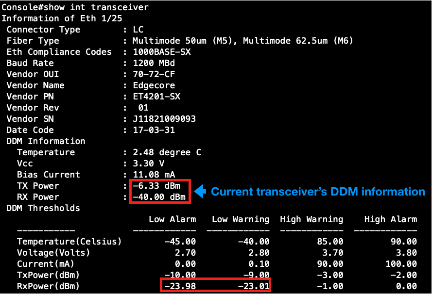
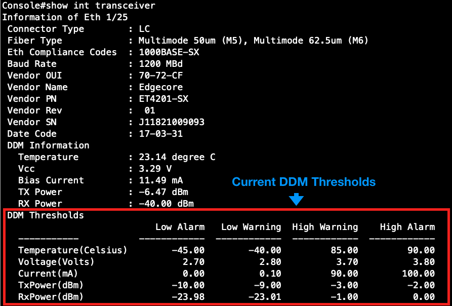
Step 2: Check the transceiver's information currently.
At this time, the RX power is not within the range of the default threshold of the Low Alarm/Waring.
Step 3: Enable the transceiver-monitor.
Console#con
Console(config)#interface ethernet 1/25
Console(config-if)#transceiver-monitor
Step 4: The switch will send out the SNMP trap (SFPThresholdAlarmWarnTrap).
The procedure to change the transceiver-threshold :
Step 1: Check the transceiver DDM Thresholds currently.
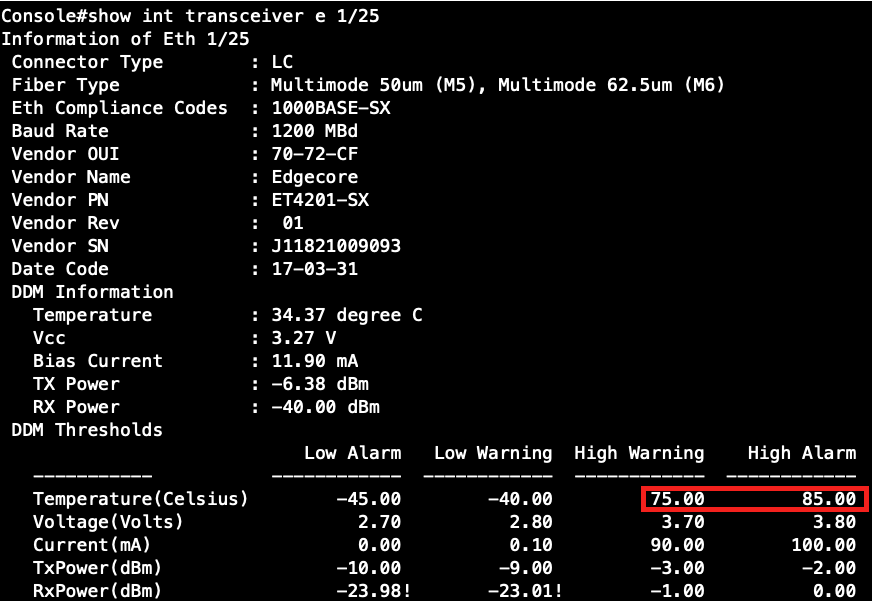
Step 2: Configure the threshold of the Temperature.
Console(config)#interface ethernet 1/25
Console(config-if)#no transceiver-threshold-auto
Console(config-if)#transceiver-threshold temperature high-warning 7500
Console(config-if)#transceiver-threshold temperature high-alarm 8500
Step 3: Check the modification of the transceiver's information.
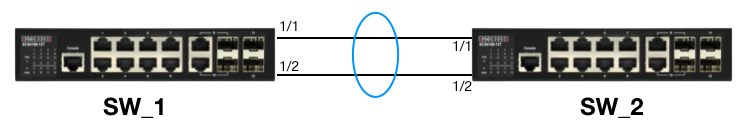
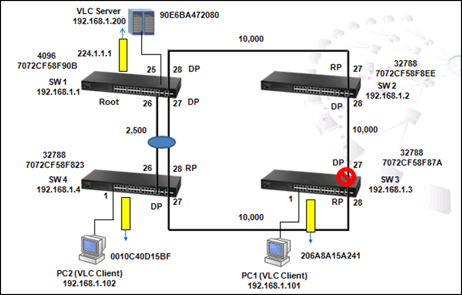
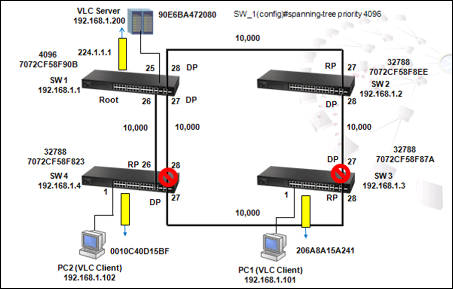
As the scenario shown below, there are two links between SW1 and SW4 and therefore two loops:
1. Loop A: SW1, SW2, SW3 and SW4
2. Loop B: SW1 and SW4.
It causes problems such as a waste of CPU utilization if more than one loop exists. In order to prevent loop, Port 26 and 27 of SW1 and Port 26 and 28 of SW4 should be trunked as a group. In this way, two links between Switch 1 and 4 will be logically identified as one link by the system and only one loop exists with port 27 of SW3 blocked.
Use the following commands to enable LACP on port 26 and 27 of SW1.
SW_1#config
SW_1(config)#interface e 1/26
SW_1(config-if)#lacp
SW_1(config-if)#int e 1/27
SW_1(config-if)#lacp
Use the command "show interface status port-channel 1" to check trunk group members. As shown below, port 26 and 27 of SW1 are member ports of trunk group 1.
SW_1#sh int status port-channel 1
Information of Trunk 1
Basic Information:
Port Type : 1000BASE-T
MAC Address : 70-72-CF-58-F9-25
Configuration:
Name :
Port Admin : Up
Speed-duplex : Auto
Capabilities : 10half, 10full, 100half, 100full, 1000full
Broadcast Storm : Enabled
Broadcast Storm Limit : 64 Kbits/second
Multicast Storm : Disabled
Multicast Storm Limit : 64 Kbits/second
Unknown Unicast Storm : Disabled
Unknown Unicast Storm Limit : 64 Kbits/second
Flow Control : Disabled
VLAN Trunking : Disabled
Current Status:
Created By : LACP
Link Status : Up
Port Operation Status : Up
Operation Speed-duplex : 1000full
Up Time : 0w 0d 0h 3m 45s (225 seconds)
Flow Control Type : None
Max Frame Size : 1518 bytes (1522 bytes for tagged frames)
Member Ports : Eth1/26, Eth1/27
Use the command "show spanning-tree port-channel 1" to check information such as role and state of each port.
SW_1#sh spanning-tree port-channel 1
Trunk 1 Information
---------------------------------------------------------------
Admin Status : Enabled
Role : Designate
State : Forwarding
Admin Path Cost : 0
Oper Path Cost : 2500
Priority : 128
Designated Cost : 0
Designated Port : 128.33
Designated Root : 4096.7072CF58F90B
Designated Bridge : 4096.7072CF58F90B
Forward Transitions : 24
Admin Edge Port : Auto
Oper Edge Port : Disabled
Admin Link Type : Auto
Oper Link Type : Point-to-point
Flooding Behavior : Enabled
Spanning-Tree Status : Enabled
Loopback Detection Status : Enabled
Loopback Detection Release Mode : Auto
Loopback Detection Trap : Disabled
Loopback Detection Action : Block
Root Guard Status : Disabled
BPDU Guard Status : Disabled
BPDU Guard Auto Recovery : Disabled
BPDU Guard Auto Recovery Interval : 300
BPDU Filter Status : Disabled
1. To prevent loop
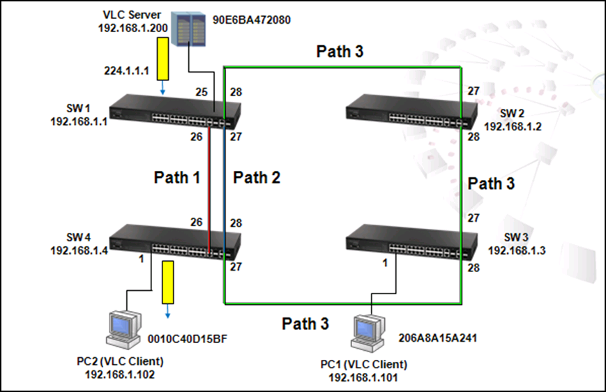
As shown in the figure above, there are 3 traffic paths from VLC server to PC2:
Path 1(red): from SW1 port 26 to SW4 port 26;
Path 2(blue): from SW1 port 27 to SW4 port 28;
Path 3(green): from SW1 port 28 to SW2 port 27, from SW2 port 28 to SW3 port 27, from SW3 port 28 to SW4 port 27 then to SW4 port 1.
Therefore, there are two loops in the topology:
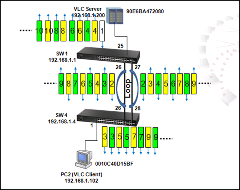
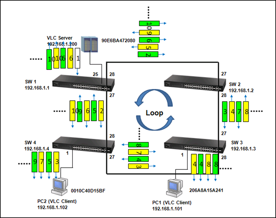
As shown in the figures above, when the switch receives a broadcast, multicast or unknown unicast packet from VCL Server, packet will flood to port 26(packet 2 yellow) and 27 (packet 2 green). When SW4 receives the packet from port 26, the packet will flood to port 1 (packet 3 yellow) and port 28 (packet 3 yellow). When SW4 receives the packet from port 28, the packet will flood to port 1(packet 3 green) and port 26 (packet 3 green). In this way, packets will occupy every port that connected to switch and it results in a failure to serving normal packets and sometimes a waste of CPU utilization.
Spanning Tree Protocol is a mechanism that automatically detects loops in the network and blocks the redundant paths to keep only one path for two nodes in the network. Rapid Spanning Tree Protocol (RSTP) is an enhancement of STP and provides faster spanning tree convergence. RSTP uses path cost, bridge ID and port priority/port ID of BPDU to prioritize the paths and then to establish a spanning tree.
2. To Provide Redundant path
Sometimes users create a loop intentionally in order to build up a redundant path in case the path is failed to link. Traffic dynamically switches to the redundant path and maintain network operation when the default path is failed to link.
When the link between SW1 port 26 and SW4 port 26 is down, SW1 port 27 which is in blocking state (Alternate Role) automatically forwards. Therefore, traffic from VLC server switches to the link between SW1 port 27 and SW4 port 28.
Use command "show log ram" to see the change log.
SW_1#sh log ram
[3] 08:59:45 2011-12-08
'STA topology change happened on Eth 1/27.'
level : 6, module : 5, function : 1, and event no. : 1
[2] 08:59:45 2011-12-08
'STP port state: MSTID 0, Eth 1/27 becomes forwarding.'
level : 6, module : 5, function : 1, and event no. : 1
[1] 08:59:45 2011-12-08
'STP port state: MSTID 0, Eth 1/26 becomes non-forwarding.'
level : 6, module : 5, function : 1, and event no. : 1
[0] 08:59:45 2011-12-08
'Unit 1, Port 26 link-down notification.'
level : 6, module : 5, function : 1, and event no. : 1
SW_4-0#sh log ram
[2] 08:28:56 2011-12-08
'STA topology change happened on Eth 1/27.'
level : 6, module : 5, function : 1, and event no. : 1
[1] 08:28:54 2011-12-08
'STP port state: MSTID 0, Eth 1/26 becomes non-forwarding.'
level : 6, module : 5, function : 1, and event no. : 1
[0] 08:28:54 2011-12-08
'Unit 1, Port 26 link-down notification.'
level : 6, module : 5, function : 1, and event no. : 1
SW_2-0#sh log ram
[1] 09:00:39 2011-12-08
'User(admin/Telnet) (192.168.1.1), login successful.'
level : 6, module : 5, function : 1, and event no. : 1
[0] 08:58:43 2011-12-08
'192.168.1.1 VTY user admin, logout from PRIV. EXEC mode.'
level : 6, module : 1, function : 0, and event no. : 1
SW_3-0#sh log ram
[2] 08:28:51 2011-12-08
'User(admin/Telnet) (192.168.1.1), login successful.'
level : 6, module : 5, function : 1, and event no. : 1
[1] 08:27:48 2011-12-08
'STA topology change happened on Eth 1/27.'
level : 6, module : 5, function : 1, and event no. : 1
[0] 08:27:12 2011-12-08
'192.168.1.1 VTY user admin, logout from PRIV. EXEC mode.'
level : 6, module : 1, function : 0, and event no. : 1
SW_4(config)#interface ethernet 1/27
SW_4(config-if)#spanning-tree port-priority ?
<0-240> Spanning-tree port priority value in steps of 16
Please note that the port priority value is steps of 16 in range of 0-240.
SW_4(config-if)#spanning-tree port-priority 16
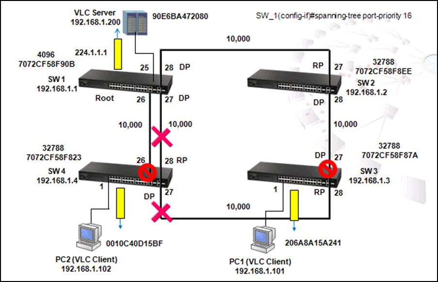

A switch is configured as root if it has the smallest priority ID. Therefore, by changing the priority ID to the smallest ID, users could configure any switch as root. For example, use the following commands to change the priority of SW1 to 4096:
SW_1(config)#spanning-tree priority?
<0-61440> Spanning-tree priority value in steps of 4096
Please note that the priority ID value can only be changed in steps of 4096, from 0 to 61440.
SW_1(config)# spanning-tree priority 4096
After changing priority ID of SW1 to 4096, SW1 is configured as the Root and the blocking port is changed to SW4 port 28 and SW3 port 27.
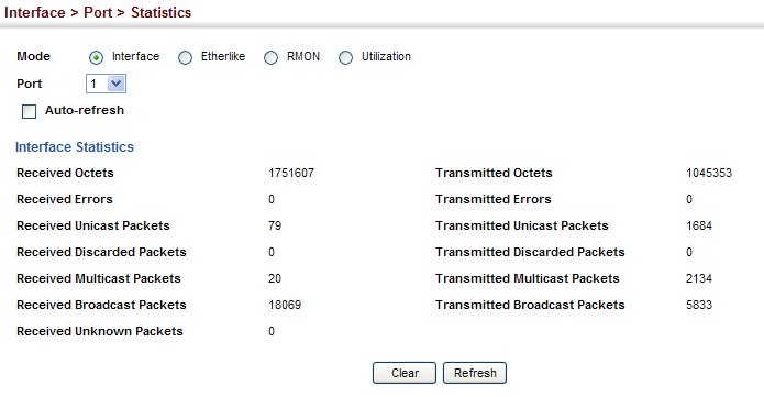
Received Octets :
1.3.6.1.2.1.31.1.1.1.6 (ifHCInOctets, 64-bit version)
1.3.6.1.2.1.2.2.1.10 (ifInOctets, 32-bit version)
C:\>snmpwalk -v 2c -c private 10.2.28.216 1.3.6.1.2.1.31.1.1.1.6.1
IF-MIB::ifHCInOctets.1 = Counter64: 1751607
C:\>snmpwalk -v 2c -c private 10.2.28.216 1.3.6.1.2.1.2.2.1.10.1
IF-MIB::ifInOctets.1 = Counter32: 1751607
Transmitted Octets :
1.3.6.1.2.1.31.1.1.1.10 (ifHCOutOctets, 64-bit version)
1.3.6.1.2.1.2.2.1.16 (ifOutOctets, 32-bit version)
C:\>snmpwalk -v 2c -c private 10.2.28.216 1.3.6.1.2.1.31.1.1.1.10.1
IF-MIB::ifHCOutOctets.1 = Counter64: 1045353
C:\>snmpwalk -v 2c -c private 10.2.28.216 1.3.6.1.2.1.2.2.1.16.1
IF-MIB::ifOutOctets.1 = Counter32: 1045353
Received Errors :
1.3.6.1.2.1.2.2.1.14 (ifInErrors)
C:\>snmpwalk -v 2c -c private 10.2.28.216 1.3.6.1.2.1.2.2.1.14.1
IF-MIB::ifInErrors.1 = Counter32: 0
Transmitted Errors :
1.3.6.1.2.1.2.2.1.20 (ifOutErrors)
ECS2100 series didn’t support this counter.
C:\>snmpwalk -v 2c -c private 10.2.28.216 1.3.6.1.2.1.2.2.1.20.1
IF-MIB::ifOutErrors.1 = No Such Instance currently exists at this OID
Received Unicast Packets :
1.3.6.1.2.1.31.1.1.1.7 (ifHCInUcastPkts, 64-bit version)
1.3.6.1.2.1.2.2.1.11 (ifInUcastPkts, 32-bit version)
C:\>snmpwalk -v 2c -c private 10.2.28.216 1.3.6.1.2.1.31.1.1.1.7.1
IF-MIB::ifHCInUcastPkts.1 = Counter64: 79
C:\>snmpwalk -v 2c -c private 10.2.28.216 1.3.6.1.2.1.2.2.1.11.1
IF-MIB::ifInUcastPkts.1 = Counter32: 79
Transmitted Unicast Packets :
1.3.6.1.2.1.31.1.1.1.11 (ifHCOutUcastPkts, 64-bit version)
1.3.6.1.2.1.2.2.1.17 (ifOutUcastPkts, 32-bit version)
C:\>snmpwalk -v 2c -c private 10.2.28.216 1.3.6.1.2.1.31.1.1.1.11.1
IF-MIB::ifHCOutUcastPkts.1 = Counter64: 1684
C:\>snmpwalk -v 2c -c private 10.2.28.216 1.3.6.1.2.1.2.2.1.17.1
IF-MIB::ifOutUcastPkts.1 = Counter32: 1684
Received Discarded Packets :
1.3.6.1.2.1.2.2.1.13 (ifInDiscards)
ECS2100 series didn’t support this counter, always return the value as 0.
C:\>snmpwalk -v 2c -c private 10.2.28.216 1.3.6.1.2.1.2.2.1.13.1
IF-MIB::ifInDiscards.1 = Counter32: 0
Transmitted Discarded Packets :
1.3.6.1.2.1.2.2.1.19 (ifOutDiscards)
C:\>snmpwalk -v 2c -c private 10.2.28.216 1.3.6.1.2.1.2.2.1.19.1
IF-MIB::ifOutDiscards.1 = Counter32: 0
Received Multicast Packets :
1.3.6.1.2.1.31.1.1.1.8 (ifHCInMulticastPkts, 64-bit version)
1.3.6.1.2.1.31.1.1.1.2 (ifInMulticastPkts, 32-bit version)
C:\>snmpwalk -v 2c -c private 10.2.28.216 1.3.6.1.2.1.31.1.1.1.8.1
IF-MIB::ifHCInMulticastPkts.1 = Counter64: 20
C:\>snmpwalk -v 2c -c private 10.2.28.216 1.3.6.1.2.1.31.1.1.1.2.1
IF-MIB::ifInMulticastPkts.1 = Counter32: 20
Transmitted Multicast Packets :
1.3.6.1.2.1.31.1.1.1.12 (ifHCOutMulticastPkts, 64-bit version)
1.3.6.1.2.1.31.1.1.1.4 (ifOutMulticastPkts, 32-bit version)
C:\>snmpwalk -v 2c -c private 10.2.28.216 1.3.6.1.2.1.31.1.1.1.12.1
IF-MIB::ifHCOutMulticastPkts.1 = Counter64: 2134
C:\>snmpwalk -v 2c -c private 10.2.28.216 1.3.6.1.2.1.31.1.1.1.4.1
IF-MIB::ifOutMulticastPkts.1 = Counter32: 2134
Received Broadcast Packets :
1.3.6.1.2.1.31.1.1.1.9 (ifHCInBroadcastPkts, 64-bit version)
1.3.6.1.2.1.31.1.1.1.3 (ifInBroadcastPkts, 32-bit version)
C:\>snmpwalk -v 2c -c private 10.2.28.216 1.3.6.1.2.1.31.1.1.1.9.1
IF-MIB::ifHCInBroadcastPkts.1 = Counter64: 18069
C:\>snmpwalk -v 2c -c private 10.2.28.216 1.3.6.1.2.1.31.1.1.1.3.1
IF-MIB::ifInBroadcastPkts.1 = Counter32: 18069
Transmitted Broadcast Packets :
1.3.6.1.2.1.31.1.1.1.13 (ifHCOutBroadcastPkts, 64-bit version)
1.3.6.1.2.1.31.1.1.1.5 (ifOutBroadcastPkts, 32-bit version)
C:\>snmpwalk -v 2c -c private 10.2.28.216 1.3.6.1.2.1.31.1.1.1.13.1
IF-MIB::ifHCOutBroadcastPkts.1 = Counter64: 5833
C:\>snmpwalk -v 2c -c private 10.2.28.216 1.3.6.1.2.1.31.1.1.1.5.1
IF-MIB::ifOutBroadcastPkts.1 = Counter32: 5833
Received Unknown Packets :
1.3.6.1.2.1.2.2.1.15 (ifInUnknownProtos)
ECS2100 series didn’t support this counter.
C:\>snmpwalk -v 2c -c private 10.2.28.216 1.3.6.1.2.1.2.2.1.15.1
IF-MIB::ifInUnknownProtos.1 = No Such Instance currently exists at this OID
QLen Output - the length of the output packet queue (in packets) :
1.3.6.1.2.1.2.2.1.21 (ifOutQLen)
ECS2100 series didn’t support this counter.
C:\>snmpwalk -v 2c -c private 10.2.28.216 1.3.6.1.2.1.2.2.1.21.1
IF-MIB::ifOutQLen.1 = No Such Instance currently exists at this OID
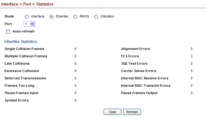
Single Collision Frames :
1.3.6.1.2.1.10.7.2.1.4 (dot3StatsSingleCollisionFrames)
C:\>snmpwalk -v 2c -c private 10.2.28.216 1.3.6.1.2.1.10.7.2.1.4.1
SNMPv2-SMI::transmission.7.2.1.4.1 = Counter32: 0
Multiple Collision Frames :
1.3.6.1.2.1.10.7.2.1.5 (dot3StatsMultipleCollisionFrames)
C:\>snmpwalk -v 2c -c private 10.2.28.216 1.3.6.1.2.1.10.7.2.1.5.1
SNMPv2-SMI::transmission.7.2.1.5.1 = Counter32: 0
Late Collisions :
1.3.6.1.2.1.10.7.2.1.8 (dot3StatsLateCollisions)
C:\>snmpwalk -v 2c -c private 10.2.28.216 1.3.6.1.2.1.10.7.2.1.8.1
SNMPv2-SMI::transmission.7.2.1.8.1 = Counter32: 0
Excessive Collisions :
1.3.6.1.2.1.10.7.2.1.9 (dot3StatsExcessiveCollisions)
C:\>snmpwalk -v 2c -c private 10.2.28.216 1.3.6.1.2.1.10.7.2.1.9.1
SNMPv2-SMI::transmission.7.2.1.9.1 = Counter32: 0
Deferred Transmissions :
1.3.6.1.2.1.10.7.2.1.7 (dot3StatsDeferredTransmissions)
C:\>snmpwalk -v 2c -c private 10.2.28.216 1.3.6.1.2.1.10.7.2.1.7.1
SNMPv2-SMI::transmission.7.2.1.7.1 = Counter32: 0
Frames Too Long :
1.3.6.1.2.1.10.7.2.1.13 (dot3StatsFrameTooLongs)
C:\>snmpwalk -v 2c -c private 10.2.28.216 1.3.6.1.2.1.10.7.2.1.13.1
SNMPv2-SMI::transmission.7.2.1.13.1 = Counter32: 0
Symbol Errors :
1.3.6.1.2.1.10.7.2.1.18 (dot3StatsSymbolErrors)
C:\>snmpwalk -v 2c -c private 10.2.28.216 1.3.6.1.2.1.10.7.2.1.18.1
SNMPv2-SMI::transmission.7.2.1.18.1 = Counter32: 0
Pause Frames Input :
1.3.6.1.2.1.10.7.10.1.3 (dot3InPauseFrames)
C:\>snmpwalk -v 2c -c private 10.2.28.216 1.3.6.1.2.1.10.7.10.1.3.1
SNMPv2-SMI::transmission.7.10.1.3.1 = Counter32: 0
Pause Frames Output :
1.3.6.1.2.1.10.7.10.1.4 (dot3OutPauseFrames)
C:\>snmpwalk -v 2c -c private 10.2.28.216 1.3.6.1.2.1.10.7.10.1.4.1
SNMPv2-SMI::transmission.7.10.1.4.1 = Counter32: 0
Alignment Errors :
1.3.6.1.2.1.10.7.2.1.2 (dot3StatsAlignmentErrors)
ECS2100 series didn’t support this counter.
C:\>snmpwalk -v 2c -c private 10.2.28.216 1.3.6.1.2.1.10.7.2.1.2.1
SNMPv2-SMI::transmission.7.2.1.2.1 = No Such Instance currently exists at this OID
FCS Errors :
1.3.6.1.2.1.10.7.2.1.3 (dot3StatsFCSErrors)
C:\>snmpwalk -v 2c -c private 10.2.28.216 1.3.6.1.2.1.10.7.2.1.3.1
SNMPv2-SMI::transmission.7.2.1.3.1 = Counter32: 0
SQE Test Errors :
1.3.6.1.2.1.10.7.2.1.6 (dot3StatsSQETestErrors)
ECS2100 series didn’t support this counter.
C:\>snmpwalk -v 2c -c private 10.2.28.216 1.3.6.1.2.1.10.7.2.1.6.1
SNMPv2-SMI::transmission.7.2.1.6.1 = No Such Instance currently exists at this OID
Carrier Sense Errors :
1.3.6.1.2.1.10.7.2.1.11 (dot3StatsCarrierSenseErrors)
ECS2100 series didn’t support this counter.
C:\>snmpwalk -v 2c -c private 10.2.28.216 1.3.6.1.2.1.10.7.2.1.11.1
SNMPv2-SMI::transmission.7.2.1.11.1 = No Such Instance currently exists at this OID
Internal MAC Receive Errors :
1.3.6.1.2.1.10.7.2.1.16 (dot3StatsInternalMacReceiveErrors)
ECS2100 series didn’t support this counter.
C:\>snmpwalk -v 2c -c private 10.2.28.216 1.3.6.1.2.1.10.7.2.1.16.1
SNMPv2-SMI::transmission.7.2.1.16.1 = No Such Instance currently exists at this OID
Internal MAC Transmit Errors :
1.3.6.1.2.1.10.7.2.1.10 (dot3StatsInternalMacTransmitErrors)
C:\>snmpwalk -v 2c -c private 10.2.28.216 1.3.6.1.2.1.10.7.2.1.10.1
SNMPv2-SMI::transmission.7.2.1.10.1 = Counter32: 0
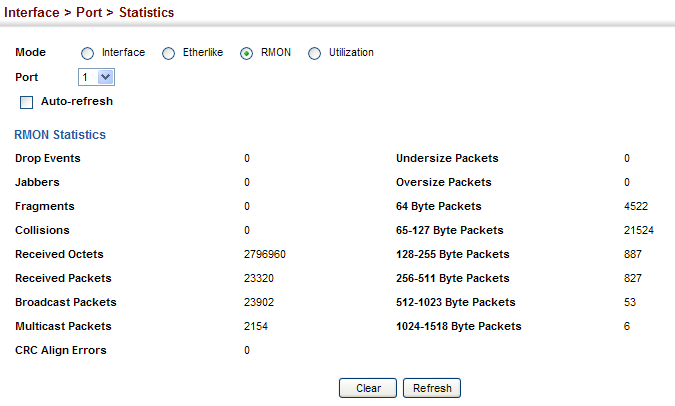
Drop Events :
1.3.6.1.2.1.16.1.1.1.3 (etherStatsDropEvents)
C:\>snmpwalk -v 2c -c private 10.2.28.216 1.3.6.1.2.1.16.1.1.1.3.1
SNMPv2-SMI::mib-2.16.1.1.1.3.1 = Counter32: 0
Jabbers :
1.3.6.1.2.1.16.1.1.1.12 (etherStatsJabbers)
C:\>snmpwalk -v 2c -c private 10.2.28.216 1.3.6.1.2.1.16.1.1.1.12.1
SNMPv2-SMI::mib-2.16.1.1.1.12.1 = Counter32: 0
Fragments :
1.3.6.1.2.1.16.1.1.1.11 (etherStatsFragments)
C:\>snmpwalk -v 2c -c private 10.2.28.216 1.3.6.1.2.1.16.1.1.1.11.1
SNMPv2-SMI::mib-2.16.1.1.1.11.1 = Counter32: 0
Collisions :
1.3.6.1.2.1.16.1.1.1.13 (etherStatsCollisions)
C:\>snmpwalk -v 2c -c private 10.2.28.216 1.3.6.1.2.1.16.1.1.1.13.1
SNMPv2-SMI::mib-2.16.1.1.1.13.1 = Counter32: 0
Received Octets :
1.3.6.1.2.1.16.1.1.1.4 (etherStatsOctets)
C:\>snmpwalk -v 2c -c private 10.2.28.216 1.3.6.1.2.1.16.1.1.1.4.1
SNMPv2-SMI::mib-2.16.1.1.1.4.1 = Counter32: 2796960
Received Packets :
1.3.6.1.2.1.16.1.1.1.5 (etherStatsPkts)
C:\>snmpwalk -v 2c -c private 10.2.28.216 1.3.6.1.2.1.16.1.1.1.5.1
SNMPv2-SMI::mib-2.16.1.1.1.5.1 = Counter32: 23320
Broadcast Packets :
1.3.6.1.2.1.16.1.1.1.6 (etherStatsBroadcastPkts)
C:\>snmpwalk -v 2c -c private 10.2.28.216 1.3.6.1.2.1.16.1.1.1.6.1
SNMPv2-SMI::mib-2.16.1.1.1.6.1 = Counter32: 23902
Multicast Packets :
1.3.6.1.2.1.16.1.1.1.7 (etherStatsMulticastPkts)
C:\>snmpwalk -v 2c -c private 10.2.28.216 1.3.6.1.2.1.16.1.1.1.7.1
SNMPv2-SMI::mib-2.16.1.1.1.7.1 = Counter32: 2154
CRC Align Errors :
1.3.6.1.2.1.16.1.1.1.8 (etherStatsCRCAlignErrors)
C:\>snmpwalk -v 2c -c private 10.2.28.216 1.3.6.1.2.1.16.1.1.1.8.1
SNMPv2-SMI::mib-2.16.1.1.1.8.1 = Counter32: 0
Undersize Packets :
1.3.6.1.2.1.16.1.1.1.9 (etherStatsUndersizePkts)
C:\>snmpwalk -v 2c -c private 10.2.28.216 1.3.6.1.2.1.16.1.1.1.9.1
SNMPv2-SMI::mib-2.16.1.1.1.9.1 = Counter32: 0
Oversize Packets :
1.3.6.1.2.1.16.1.1.1.10 (etherStatsOversizePkts)
C:\>snmpwalk -v 2c -c private 10.2.28.216 1.3.6.1.2.1.16.1.1.1.10.1
SNMPv2-SMI::mib-2.16.1.1.1.10.1 = Counter32: 0
64 Byte Packets :
1.3.6.1.2.1.16.1.1.1.14 (etherStatsPkts64Octets)
C:\>snmpwalk -v 2c -c private 10.2.28.216 1.3.6.1.2.1.16.1.1.1.14.1
SNMPv2-SMI::mib-2.16.1.1.1.14.1 = Counter32: 4522
65-127 Byte Packets :
1.3.6.1.2.1.16.1.1.1.15 (etherStatsPkts65to127Octets)
C:\>snmpwalk -v 2c -c private 10.2.28.216 1.3.6.1.2.1.16.1.1.1.15.1
SNMPv2-SMI::mib-2.16.1.1.1.15.1 = Counter32: 21524
128-255 Byte Packets :
1.3.6.1.2.1.16.1.1.1.16 (etherStatsPkts128to255Octets)
C:\>snmpwalk -v 2c -c private 10.2.28.216 1.3.6.1.2.1.16.1.1.1.16.1
SNMPv2-SMI::mib-2.16.1.1.1.16.1 = Counter32: 887
256-511 Byte Packets :
1.3.6.1.2.1.16.1.1.1.17 (etherStatsPkts256to511Octets)
C:\>snmpwalk -v 2c -c private 10.2.28.216 1.3.6.1.2.1.16.1.1.1.17.1
SNMPv2-SMI::mib-2.16.1.1.1.17.1 = Counter32: 827
512-1023 Byte Packets :
1.3.6.1.2.1.16.1.1.1.18 (etherStatsPkts512to1023Octets)
C:\>snmpwalk -v 2c -c private 10.2.28.216 1.3.6.1.2.1.16.1.1.1.18.1
SNMPv2-SMI::mib-2.16.1.1.1.18.1 = Counter32: 53
1024-1518 Byte Packets :
1.3.6.1.2.1.16.1.1.1.19 (etherStatsPkts1024to1518Octets)
C:\>snmpwalk -v 2c -c private 10.2.28.216 1.3.6.1.2.1.16.1.1.1.19.1
SNMPv2-SMI::mib-2.16.1.1.1.19.1 = Counter32: 6
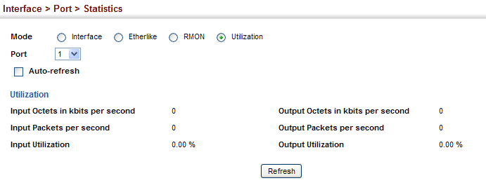
Input Octets in kbits per second :
1.3.6.1.4.1.259.10.1.43.1.2.6.1.2 (portInOctetRate)
C:\>snmpwalk -v 2c -c private 10.2.28.216 1.3.6.1.4.1.259.10.1.43.1.2.6.1.2.1
SNMPv2-SMI::enterprises.259.10.1.43.1.2.6.1.2.1 = Counter64: 0
Input Packets per second :
1.3.6.1.4.1.259.10.1.43.1.2.6.1.3 (portInPacketRate)
C:\>snmpwalk -v 2c -c private 10.2.28.216 1.3.6.1.4.1.259.10.1.43.1.2.6.1.3.1
SNMPv2-SMI::enterprises.259.10.1.43.1.2.6.1.3.1 = Counter64: 0
Input Utilization :
1.3.6.1.4.1.259.10.1.43.1.2.6.1.4 (portInUtil)
C:\>snmpwalk -v 2c -c private 10.2.28.216 1.3.6.1.4.1.259.10.1.43.1.2.6.1.4.1
SNMPv2-SMI::enterprises.259.10.1.43.1.2.6.1.4.1 = INTEGER: 0
Output Octets in kbits per second :
1.3.6.1.4.1.259.10.1.43.1.2.6.1.5 (portOutOctetRate)
C:\>snmpwalk -v 2c -c private 10.2.28.216 1.3.6.1.4.1.259.10.1.43.1.2.6.1.5.1
SNMPv2-SMI::enterprises.259.10.1.43.1.2.6.1.5.1 = Counter64: 0
Output Packets per second :
1.3.6.1.4.1.259.10.1.43.1.2.6.1.6 (portOutPacketRate)
C:\>snmpwalk -v 2c -c private 10.2.28.216 1.3.6.1.4.1.259.10.1.43.1.2.6.1.6.1
SNMPv2-SMI::enterprises.259.10.1.43.1.2.6.1.6.1 = Counter64: 0
Output Utilization :
1.3.6.1.4.1.259.10.1.43.1.2.6.1.7 (portOutUtil)
C:\>snmpwalk -v 2c -c private 10.2.28.216 1.3.6.1.4.1.259.10.1.43.1.2.6.1.7.1
SNMPv2-SMI::enterprises.259.10.1.43.1.2.6.1.7.1 = INTEGER: 0
Model Name: ECS4620 series
Firmware Version: v1.2.2.19
1. Set privilege-8, privilege-15 accounts and enable password in tacacs Server
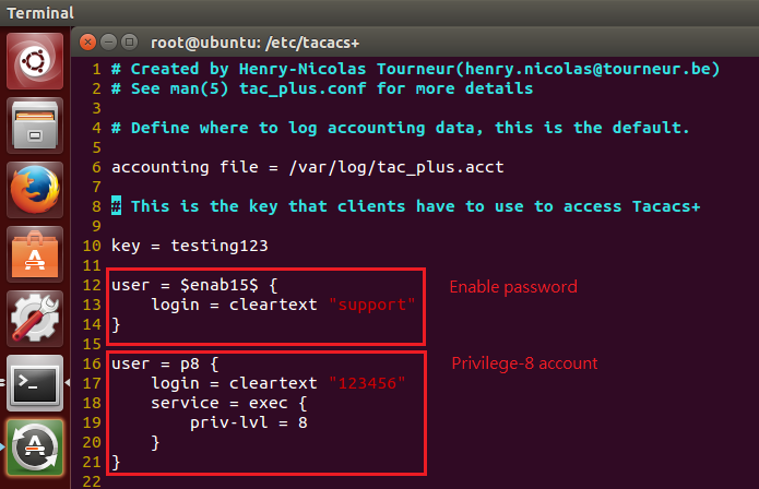
2. Then, set following command:
Console(config)#tacacs-server 1 host [tacacs server ip] key [tacacs server's key]
Console(config)#authentication login tacacs local
Console(config)#authentication enable tacacs local
Console(config)#line console
Console(config-line-console)#authorization exec default

3. Use privilege-8 account login to switch, and use enable to access privilege-15
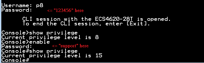
PS. If you want use telnet login, you need to use “authorization exec default” in line vty, too.
Console#show privilege
Current privilege level is 15
Console#configure
Console(config)#line vty
Console(config-line-vty)#authorization exec default
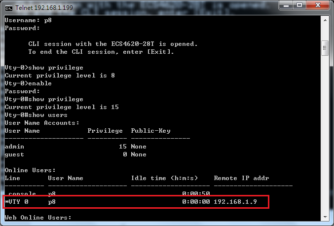
When the user changes the default login method to use no username, the user will only need to enter the password.
- Topology:
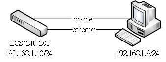
- Switch configure:
- Reset switch to default.
Console(config)#boot system config:Factory_Default_Config.cfg
Console(config)#
Console#reload
System will be restarted. Continue

- Set line console/vty password
Console(config)#line console
Console(config-line-console)#password 0 support
Console(config-line-console)#login
Console(config-line-console)#exit
Console(config)#line vty
Console(config-line-vty)#password 0 support
Console(config-line-vty)#login
Console(config-line-vty)#
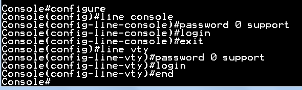
- Verify

When the user logs in with the password set for console/vty, the user’s privilege level is 0. The user needs to use the command “enable” to get privilege level -15.
Default enable password is “super”.
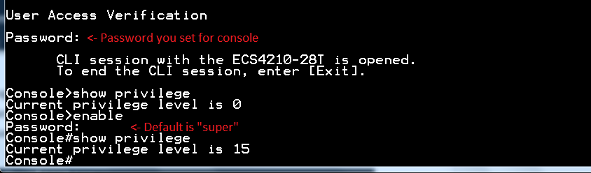
Model: AS5710-54X-EC
Console(config-router)#neighbor x.x.x.x description Edge-Core
Failed to set neighbor description.
Console(config-router)#
Solution:
Users have to set “neighbor remote-as”. After that, users are able to set the BGP neighbor description.
Console#con
Console(config)#router bgp 1
Console(config-router)#neighbor 192.168.1.2 remote-as 2
Console(config-router)#neighbor 192.168.1.2 description Edge-Core
Console(config-router)#
Answer: The AS5710-54X-EC supports 3 BGP log messages.
- BGP_NEIGHBOR_CHANGE_MESSAGE "BGP: %s"
- BGP_ESTABLISHED_NOTIFICATION_MESSAGE "BGP established, ip: %s, last err: 0x%04x, state: %s"
- BGP_BACKWARD_TRANS_NOTIFICATION_MESSAGE "BGP backward trans, ip: %s, last err: 0x%04x, state: %s"
No, all the Edgecore switches unit ID start from 1.
For some stackable switches (ex, ECS4510, ECS4620), which may have 4 units in a stack for management. Then the unit ID is from 1 to 4.
For example:
If the client connects on port2 of second unit in stack, the interface would be "eth 2/2".
Scenario:
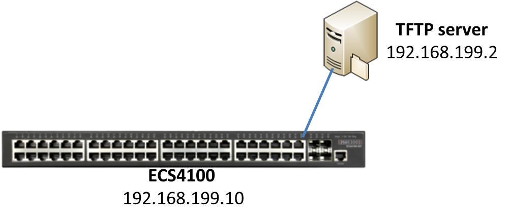
Procedures:
1. Upload the firmware to the TFTP server and specify the file name to “ECS4100-series.bix”.

2. Configure the IP address on switch. (The management IP address is 192.168.2.10/24 by default.)
Console#configure
Console(config)#interface vlan 1
Console(config-if)#ip address 192.168.199.10/24
3. Enable the auto-upgrade function on global mode.
Console(config)#upgrade opcode auto
Console(config)#upgrade opcode reload
4. Configure the directory path of TFTP server.
Console(config)#upgrade opcode path tftp://192.168.199.2/
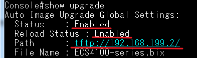
5. Save the configuration file.
Console#copy running-config startup-config
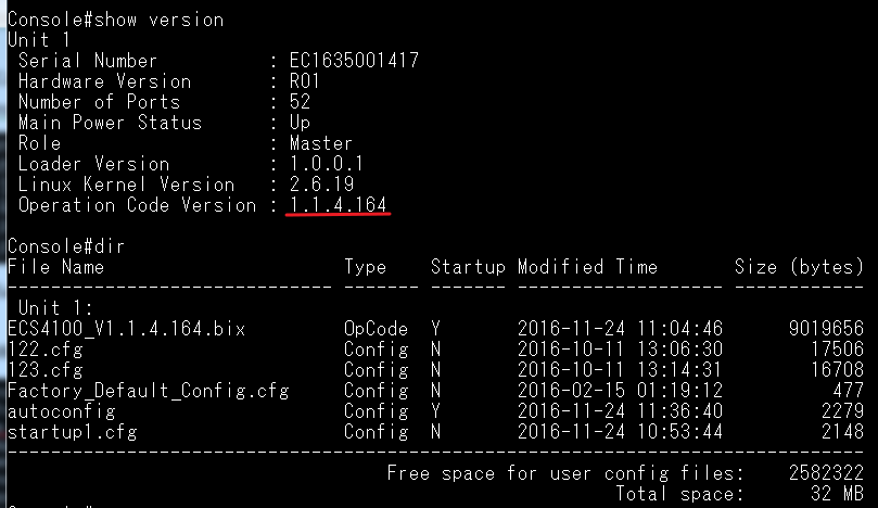
6. Reboot the switch.

7. The switch will look for newer firmware version after rebooting. If there is a newer firmware, the switch will auto upgrade and restart the system.
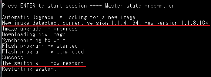
8. Now, the switch boots up with newer version.
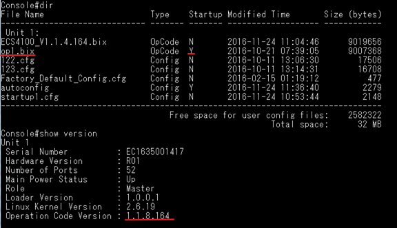
Scenario:
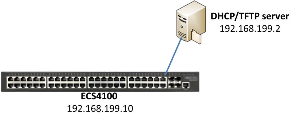
Introduction:
When the switch obtains the IP address from the DHCP server, it will download the configuration from TFTP server and apply the configuration automatically.
Procedures:
1. Put the configuration file to the TFTP server.
2. The DHCP server must setup the option 66(TFTP server name) and 67 (Bootfile name).
For Example:
Serva32.exe is a free software tool which contain DHCP and TFTP server. (http://www.vercot.com/~serva/)
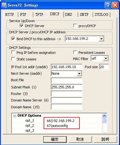
3. DHCP options is disable by default. The user has to enable the “DHCP Dynamic Provision” on global mode.
Console#configure
Console(config)#ip dhcp dynamic-provision
4. Configure the switch to obtain management IP address from the DHCP server.
Console(config)#interface vlan 1
Console(config-if)#ip address dhcp
5. The switch sends the DHCP discover packet to acquire an IP address.
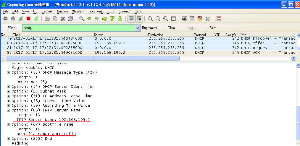
6. When switch obtain the IP address, it will start to download the configuration file from the TFTP server and apply the configuration automatically.
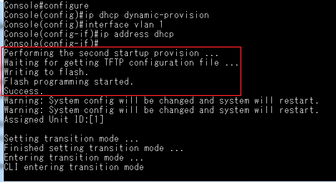
*The configuration file will be set to the startup file automatically.
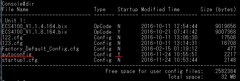
Cable Diagnostic supports either (A) cable failures, as well as the status and approximate distance to a fault or (B) the approximate cable length if no fault is found.
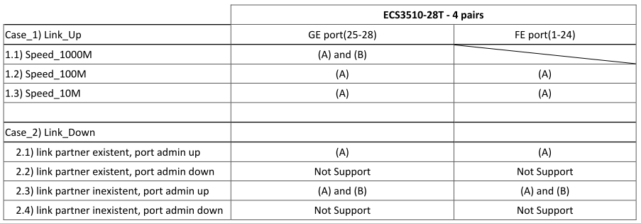
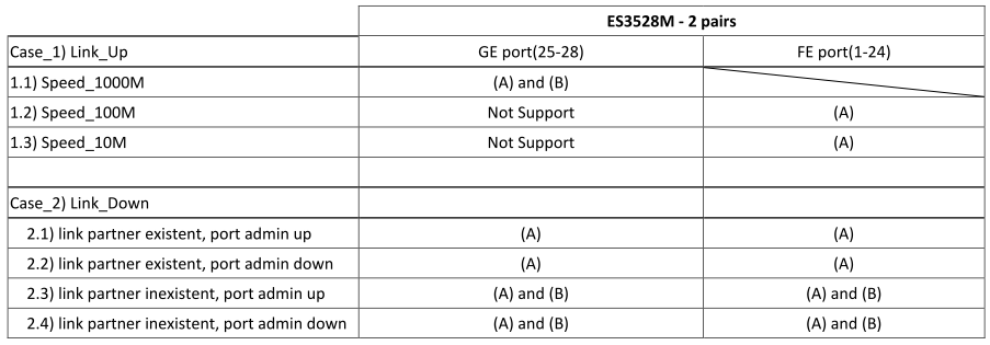
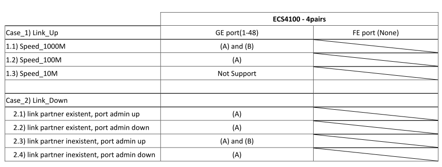
System info:
Ubuntu 16.04.2 LTS (Desktop, amd64)
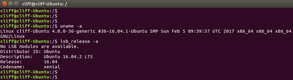
Package info:
- snmpd v5.7.3
- mrtg v2.17.4
- apache2 v2.4.18
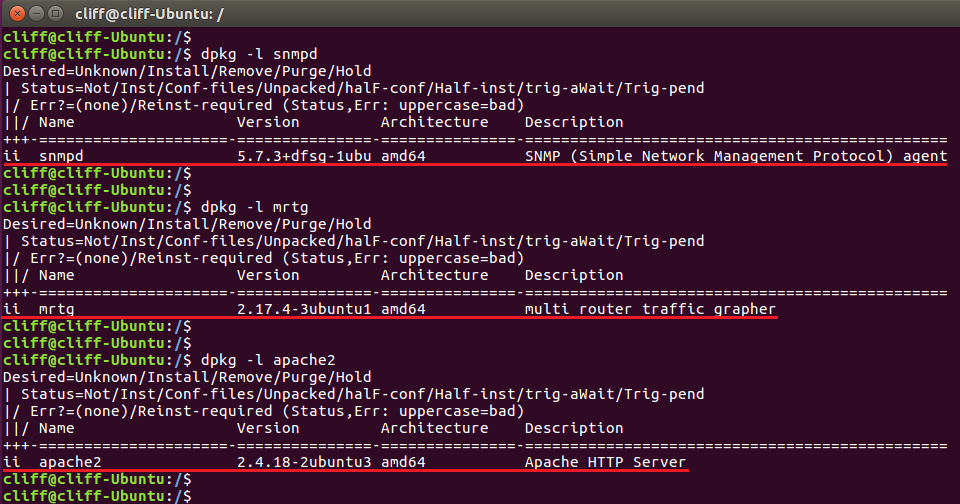
Install and configure steps:
0. Update the source package list
sudo apt-get update
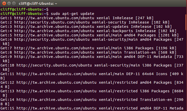
1. snmpd
1-1 Install packages
sudo apt-get install snmp
sudo apt-get install snmpd
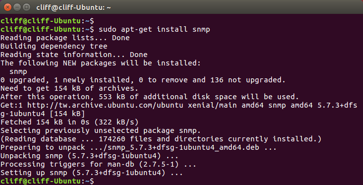
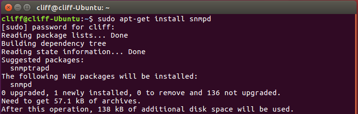
1-2 Creat snmp community word
echo 'rocommunity public' > /etc/snmp/snmpd.conf
1-3 Restart the snmpd service
service snmpd restart
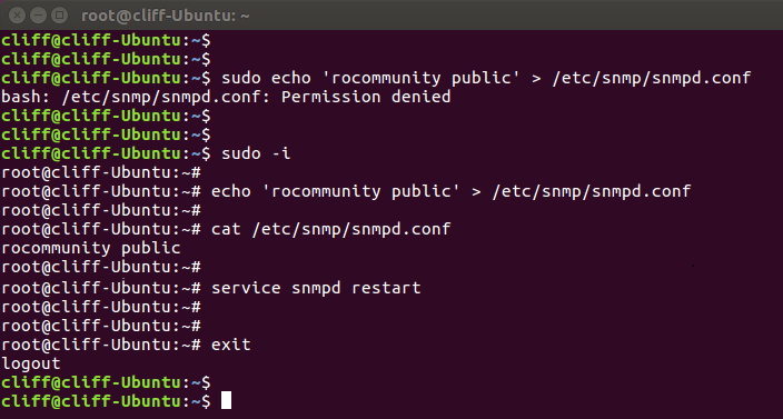
1-4 Test snmpd (Can get OIDs)
snmpwalk localhost –v 1 –c public
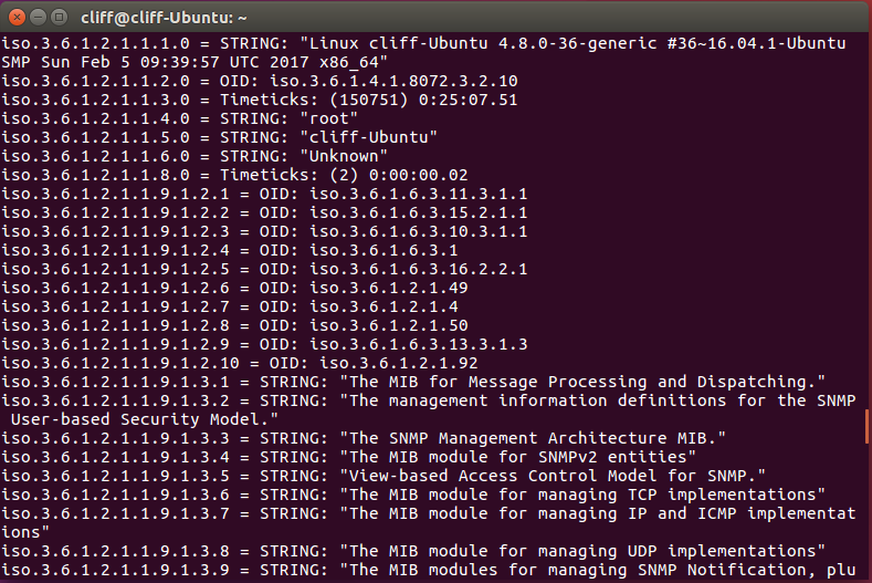
Reference:
http://www.debianhelp.co.uk/snmp.htm
http://www.net-snmp.org/docs/readmefiles.html
2. mrtg
2-1 Install mrtg
sudo apt-get install mrtg
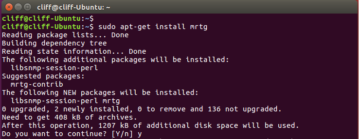
2-2 Configure mrtg.cfg
sudo vi /etc/mrtg.cfg
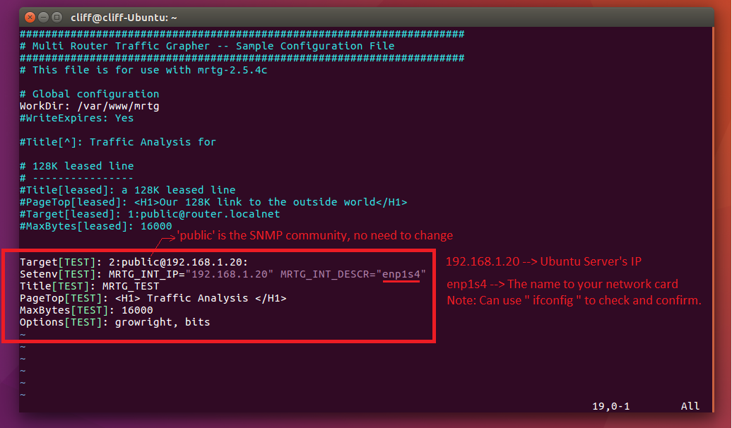
3. apache2
3-1 Install apache2
sudo apt-get install apache2
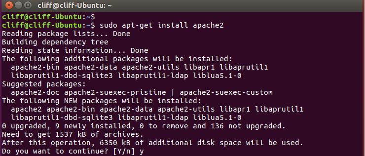
3-2 Configure apache2.cfg
sudo vi /etc/apache2/apache2.cfg
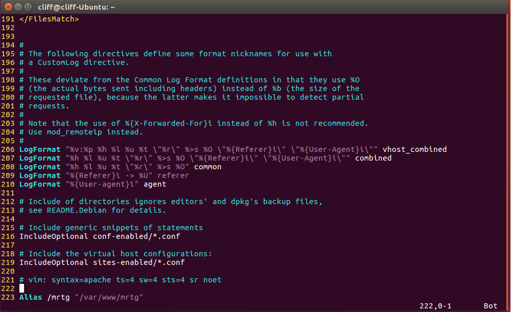
In the end of this file, add Alias /mrtg “/var/www/mrtg”to link URL to file.
Syntax: Alias URL-path file-path/directory-path
3-3 Creat new folder to save MRTG data
sudo mkdir /var/www/mrtg
3-4 Creat MRTG data (Need execute 3 times)
sudo env LANG=C /usr/bin/mrtg /etc/mrtg.cfg
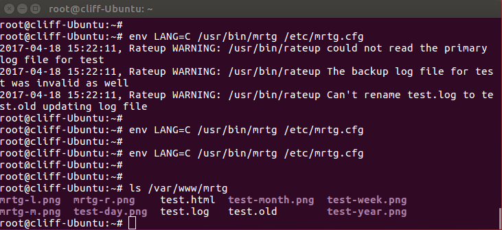
If success, you can find the data under /var/www/mrtg/
3-5 Link test.html to index.html
sudo ln –s /var/www/mrtg/test.html /var/www/mrtg/index.html
This command can use http://192.168.1.20/mrtg to access the MRTG page.
No need to use http://192.168.1.20/mrtg/test.html to access this page.
3-6 Restart apache web service
service apache2 restart
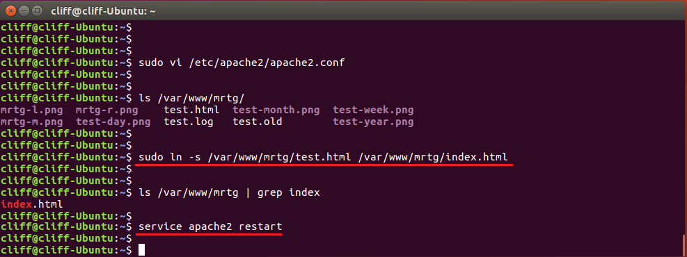
Result:
Now can access the MRTG statistic page ( http:// Ubuntu_server 's IP/mrtg )
This page will refresh per 5 min.
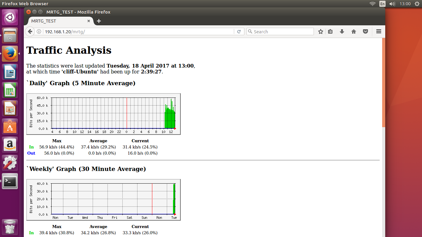
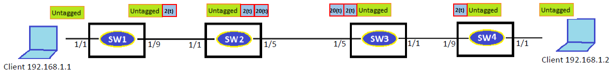
Firmware Version: 1.5.1.18
IEEE 802.1Q tunneling (QinQ tunneling) uses a single Service Provider VLAN (SPVLAN) for customers who have multiple VLANs.
QinQ tunneling expands VLAN space by using a VLAN-in-VLAN hierarchy, preserving the customer’s original tagged packets, and adding SPVLAN tags to each frame (also called double tagging).
At SW 1 and SW4
1. Configure access mode
Console(config)#interface ethernet 1/1
Console(config-if)#switchport mode access
Console(config-if)#switchport native vlan 2
Console(config-if)#switchport allowed vlan remove 1
2. Configure trunk mode
Console(config)#interface ethernet 1/9
Console(config-if)#switchport mode trunk
Console(config-if)#switchport allowed vlan add 2 tagged
Console(config-if)#switchport allowed vlan remove 1
At SW2 and SW3
1. Enable QinQ
Console(config)#dot1q-tunnel system-tunnel-control
2. Configure Q-in-Q access port
Console(config)interface ethernet 1/1
Console(config-if)#switchport allowed vlan add 20 untagged
Console(config-if)#switchport native vlan 20
Console(config-if)#switchport allowed vlan remove 1
Console(config-if)#switchport dot1q-tunnel mode access
3. Configure Q-in-Q uplink port
Console(config)interface ethernet 1/5
Console(config-if)#switchport allowed vlan add 20 tagged
Console(config-if)#switchport dot1q-tunnel mode uplink
Check the status on the switch
Console#show dot1q-tunnel
802.1Q Tunnel Status : Enabled
Port Mode TPID (Hex) Priority Mapping
-------- ------ ---------- ----------------
Eth 1/ 1 Access 8100 Disabled
Eth 1/ 2 Normal 8100 Disabled
Eth 1/ 3 Normal 8100 Disabled
Eth 1/ 4 Normal 8100 Disabled
Eth 1/ 5 Uplink 8100 Disabled
Eth 1/ 6 Normal 8100 Disabled
Eth 1/ 7 Normal 8100 Disabled
Eth 1/ 8 Normal 8100 Disabled
Eth 1/ 9 Normal 8100 Disabled
Eth 1/ 10 Normal 8100 Disabled
The packet, captured from SW1 to SW2.
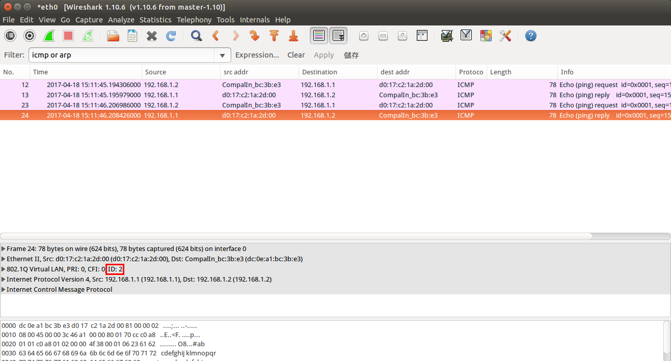
The packet, captured from SW2 to SW3.
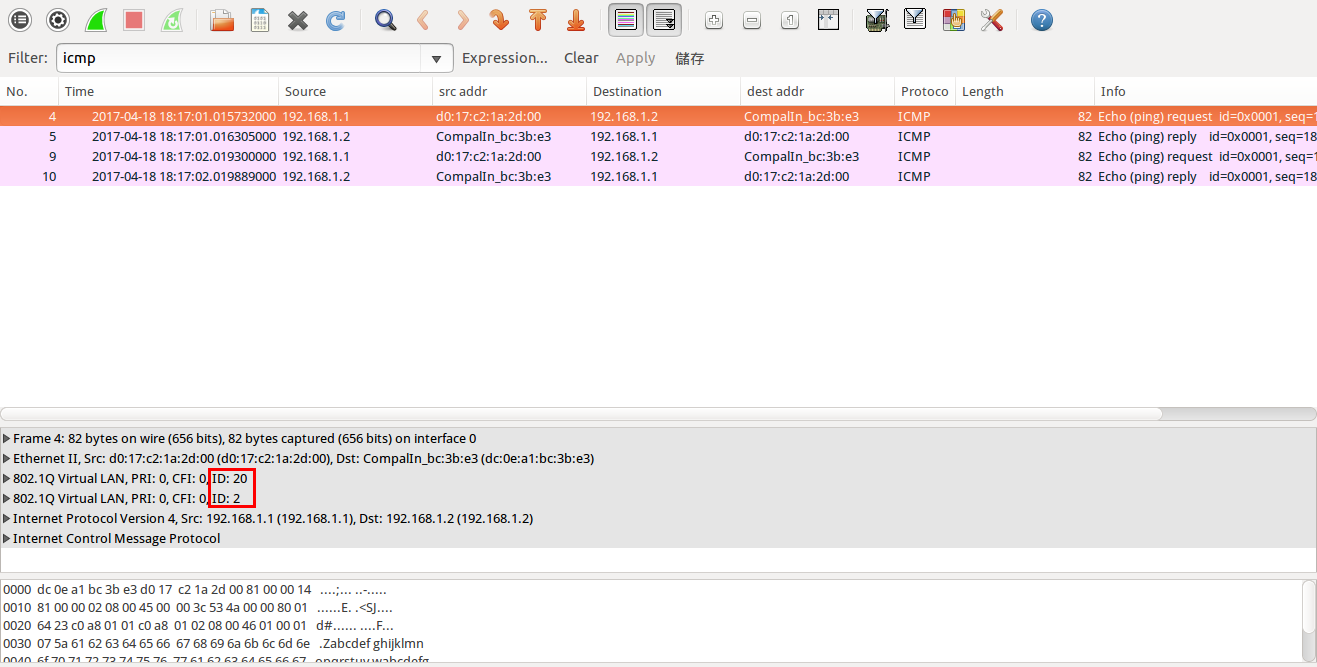
The packet, captured from SW3 to SW4.
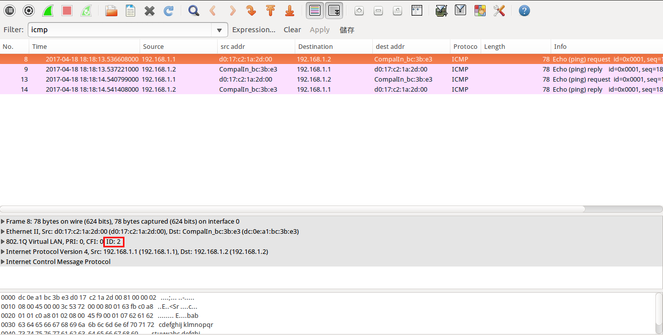
However, user may enable/disable PoE function via standard MIB - POWER-ETHERNET-MIB.
SNMPSET command format:
snmpset -v 2c -c public <switch ip> <pethPsePortAdminEnable>.<pethPsePortGroupIndex>.<pethPsePortIndex> <integer> <value>
pethPsePortAdminEnable = true(1), false(2)
For example:
Disabled PoE function on eth1/3.
(1) pethPsePortAdminEnable (Integer 2 : false)
C:\>snmpset -v 2c -c private 192.168.1.1 1.3.6.1.2.1.105.1.1.1.3.1.3 i 2
SNMPv2-SMI::mib-2.105.1.1.1.3.1.3 = INTEGER: 2
Result
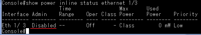
Support model: ECS4620 Series, ECS4510 Series, ECS4120 Series, ECS4100 Series, ECS4110 Series, ECS4210, ECS3500 Series, ECS2100 Series,
When Traffic segmentation is enabling, then
- Ping from 192.168.1.101 to 192.168.1.102 will fail. (downlink port to downlink port)
- Ping from 192.168.1.101 to 192.168.1.112 will pass. (downlink port to uplink port)
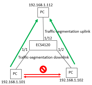
Setting traffic-segmentation
Console(config)#traffic-segmentation uplink ethernet 1/12
Console(config)#traffic-segmentation downlink ethernet 1/1-2
Console(config)#traffic-segmentation
Console(config)#end
Console#show traffic-segmentation
Traffic segmentation Status : Enabled
Uplink-to-Uplink Mode : Blocking
Session Uplink Ports Downlink Ports
--------- ------------------------------ -----------------------------
1 Ethernet 1/12 Ethernet 1/1
Ethernet 1/2
Test:
When Traffic segmentation Status shows Enabled,
- Ping from 192.168.1.101 to 192.168.1.102 will fail.
- Ping from 192.168.1.101 to 192.168.1.112 will pass.
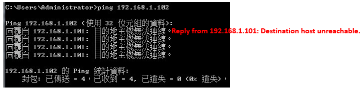
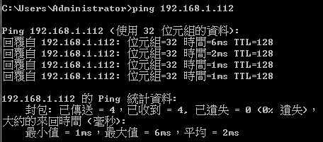
When Traffic segmentation Status shows Disable,
- Ping from 192.168.1.101 to 192.168.1.102 will pass.
- Ping from 192.168.1.101 to 192.168.1.112 will pass too.
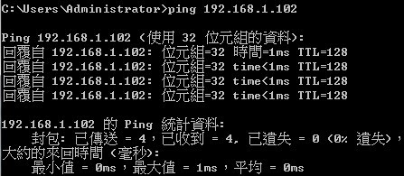
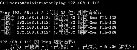
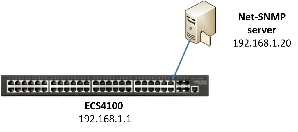
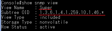
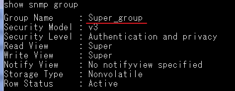
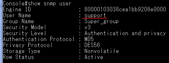
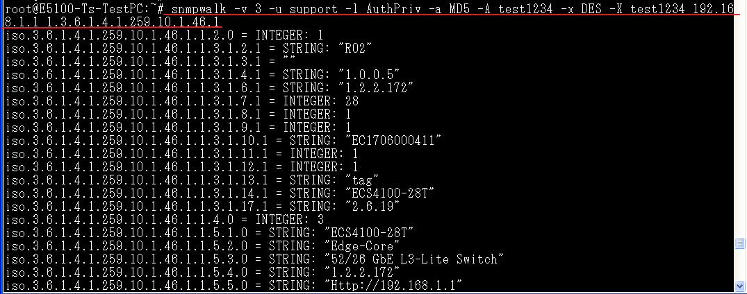
The Key difference for those two are the multicast data received on the clients.
For example, please find the basic MVR configuration on the switch.

L2 MVR design
When the switch enables MVR function and the status becomes "Active", the MVR receiver port will join the MVR VLAN as member automatically.
Once the client joins the multicast group, the client could receive the multicast data with MVR VLAN tagged (trunk mode) or untagged (hybrid mode).
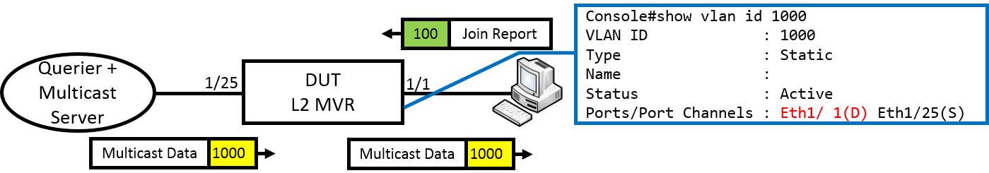
Models: ECS4620 series, ECS4510 series, ECS4120 series, ECS4100 series, ECS4110 series, ECS4210 series, ECS3510-28T/52T, ES3528Mv2, ES3510MA
L3 MVR design
MVR receiver port will NOT join the MVR VLAN as member automatically when the MVR function is active.
When the client joins the multicast group, the multicast data with MVR VLAN will replace the VLAN tag to client VLAN and forward to the port.

Models: ECS4660-28F, ECS4610-24F, ECS4610-26T/50T
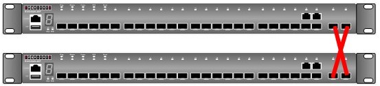
Console#switch stacking-port option ?
<1-2> the option of stacking port
(option 1 is front 10G ports such as port 25-26 in ECS4510-28T or ECS4620-28T )
Console#switch stacking-port option 1 ?
<1-8> unit number
Console#switch stacking-port option 1 1
After setting, please reload the switch.
You can check the setting by using “show stacking-port option” command.
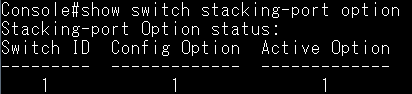
rear 10G ports

Console#switch stacking-port option ?
<1-2> the option of stacking port
(option 2 is rear 10G ports such as port 27-28 in ECS4510-28T or ECS4620-28T )
Console#switch stacking-port option 2 ?
<1-8> unit number
Console#switch stacking-port option 2 1
After setting, please reload the switch.
You can check the setting by using “show switch stacking-port option” command.
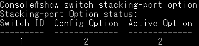
A config example show as below,
ECS4510 series
==== Create the class-map for VLAN classification ====
ECS4510(config)# class-map test
ECS4510(config-cmap)# match vlan 1
========================================
==== policy-map for traffic limation ====
ECS4510(config)# policy-map VLAN1_limit
ECS4510(config-pmap)# class test
ECS4510(config-pmap-c)# police flow 10000 1600000 conform-action transmit
violate-action drop (Restricted to 10 Mbps, and drop packets if exceeded)
================================================================
==== Apply this policy-map to the ports (input for ingress, output for egress)====
ECS4510(config)# interface ethernet 1/1
ECS4510(config-if)# service-policy input VLAN1_limit
==============================================
==== Check the configuration ====
ECS4510# show policy-map
Policy Map VLAN1_limit
Description:
class test
police flow 10000 1600000 conform-action transmit violate-action drop
ECS4510# show policy-map interface 1/1 input
Service-policy VLAN1_limit
============================
Topology shows as below:
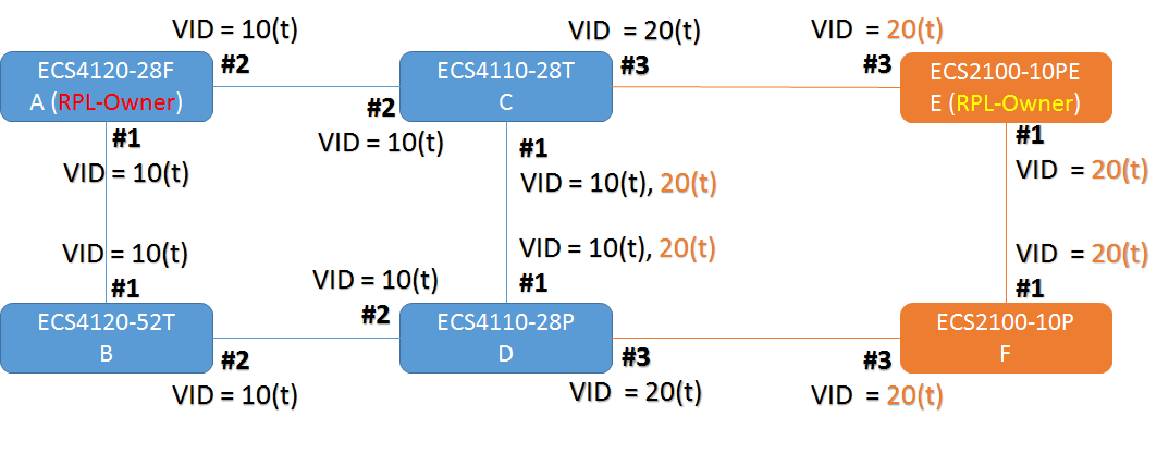
Major Ring (Domain): Switch A is RPL Owner for major ring.
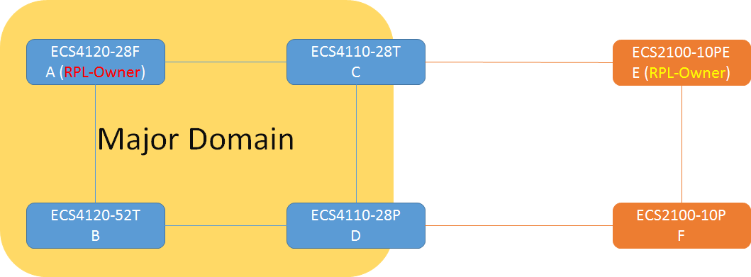
Sub Ring (Domain): Switch E is RPL owner for sub ring.
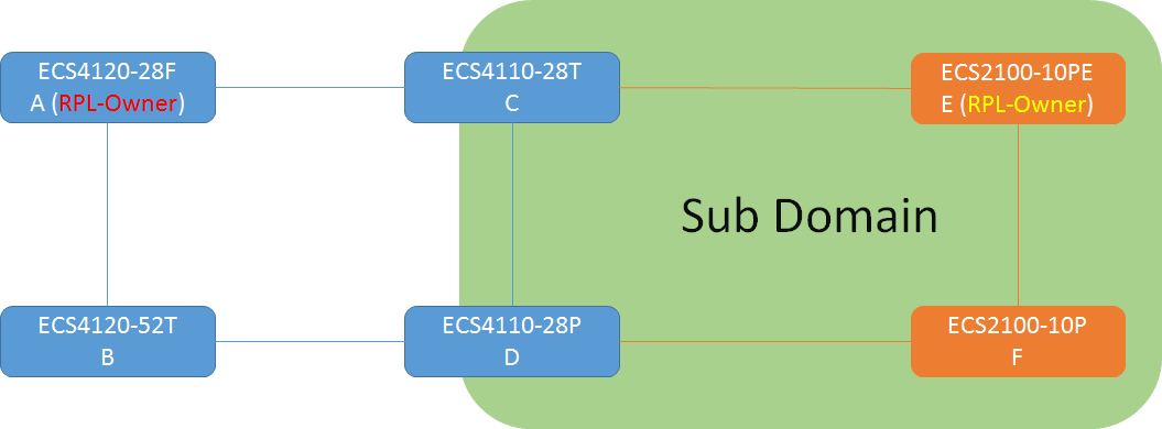
Blocking port
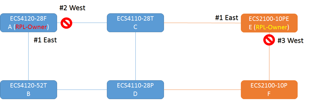
Configuration:
- Major Ring
Switch A:
A(config)#erps
A(config)#erps domain major
A(config-erps)#control-vlan 10
A(config-erps)#ring-port east interface ethernet 1/1
A(config-erps)#ring-port west interface ethernet 1/2
A(config-erps)#rpl owner
A(config-erps)#enable
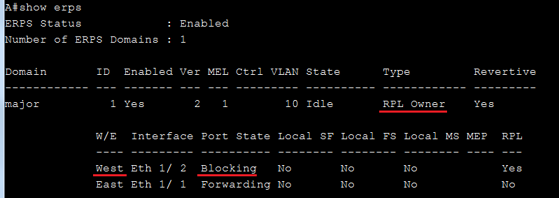
Switch B: (The configuration of Switch C & Switch D are the same as Switch B)
B(config)#erps
B(config)#erps domain major
B(config-erps)#control-vlan 10
B(config-erps)#ring-port east interface ethernet 1/1
B(config-erps)#ring-port west interface ethernet 1/2
B(config-erps)#enable
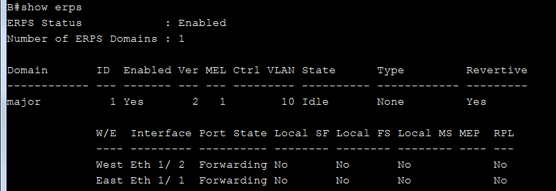
- Sub Ring
- Need to assign major domain by “major-domain” command.
- Assign only one ring-port.
C(config)#erps
C (config)#erps domain sub
C (config-erps)#major-domain major
C (config-erps)#control-vlan 20
C (config-erps)#ring-port west interface ethernet 1/3
C (config-erps)#enable
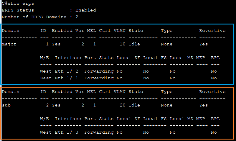
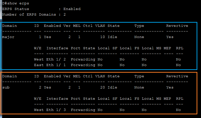
Switch E:
E(config)#erps
E(config)#erps domain sub
E(config-erps)#control-vlan 20
E(config-erps)#ring-port east interface ethernet 1/1
E(config-erps)#ring-port west interface ethernet 1/3
E(config-erps)#rpl owner
E(config-erps)#enable
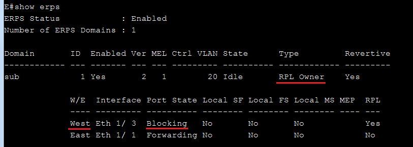
Switch F:
F(config)#erps
F(config)#erps domain sub
F(config-erps)#control-vlan 20
F(config-erps)#ring-port east interface ethernet 1/1
F(config-erps)#ring-port west interface ethernet 1/3
F(config-erps)#enable
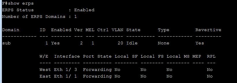
Models: ECS4620 series, ECS4510 series, ECS4120 series, ECS4100 series, ECS4110 series, ECS4210 series, ECS3510-28T/52T, ES3528Mv2, ES3510MA, ECS2100 series
When users try to get the current operational state of the interface by SNMP, the OID should be ifOperStatus (1.3.6.1.2.1.2.2.1.8).
There are two kind of results, “lowerLayerDown(7)” and “down(2)”.
IF-MIB::ifOperStatus.25 = INTEGER: lowerLayerDown(7)
IF-MIB::ifOperStatus.1001 = INTEGER: down(2)
What's the difference between "lowerLayerDown" and "down" status?
(1) lowerLayerDown: If “operstatus” is not able to change to UP, and the cause is due to PHY link is down, it will display lowerlayerdown.
For example, no cable connected or admin down/manual shutdown. (In current design, it will shut down PHY) or shut down by the specific functions below.
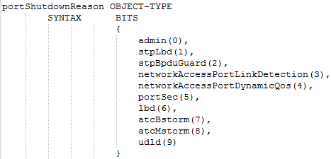
(2) down: If the operstatus is not able to change to UP and the cause is NOT due to the PHY link is down, it will display down.
For example, vlan adminstatus down.
Console#sh ip int
VLAN 1 is Administrative Up - Link Down
Address is CC-37-AB-94-80-20
Index: 1001, MTU: 1500
Address Mode is User specified
IP Address: 192.168.2.10 Mask: 255.255.255.0
Proxy ARP is disabled
DHCP Client Vendor Class ID (text): ECS2100-10T
DHCP Relay Server:
Console#
support model: ECS4620 Series, ECS4510 Series, ECS4120 Series, ECS4100 Series, ECS4110 Series, ECS4210, ECS3500 Series, ECS2100 Series, ECS2110 Series
Switch Clustering:
Switch Clustering is a method of grouping switches together to enable centralized management through a single unit.
What’s Cluster Commander and Cluster Member?
A switch cluster has a primary unit called the “Commander” which is used to manage all other “Member” switches in the cluster.
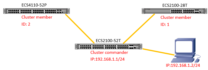
The steps to configure on ECS2100-28T and ECS4110-52P:
ECS2100-28T(config)#cluster (enables clustering on the switch.)
ECS4110-52P(config)#cluster
The steps to configure on ECS2100-52T:
ECS2100-52T(config)#int vlan 1
ECS2100-52T (config-if)#ip address 192.168.1.1/24
ECS2100-52T (config)#cluster
ECS2100-52T (config)#cluster ip-pool 10.1.2.1
(IP pool is used to assign IP addresses to Member switches in the cluster. Cluster IP addresses are in the form 10.x.x.x)
ECS2100-52T (config)#cluster commander (enables the switch as a cluster Commander.)
ECS2100-52T (config)#exit
ECS2100-52T#show cluster candidates
Cluster Candidates:
Role MAC Address Description
--------------- ----------------- -----------------------------------------
Candidate 00-E0-0C-11-CC-00 ECS2100-28T
Candidate CC-37-AB-42-6F-B8 ECS4110-52P
ECS2100-52T#configure
ECS2100-52T(config)#cluster member mac-address 00-E0-0C-11-CC-00 id 1
(configures a Candidate switch as a cluster Member.)
ECS2100-52T(config)#cluster member mac-address CC-37-AB-42-6F-B8 id 2
ECS2100-52T(config)#exit
After setting, you can check the member by using “show cluster members” command.
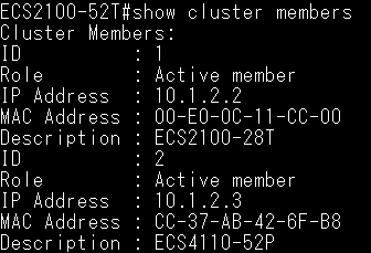
Test via telnet.
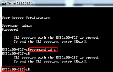
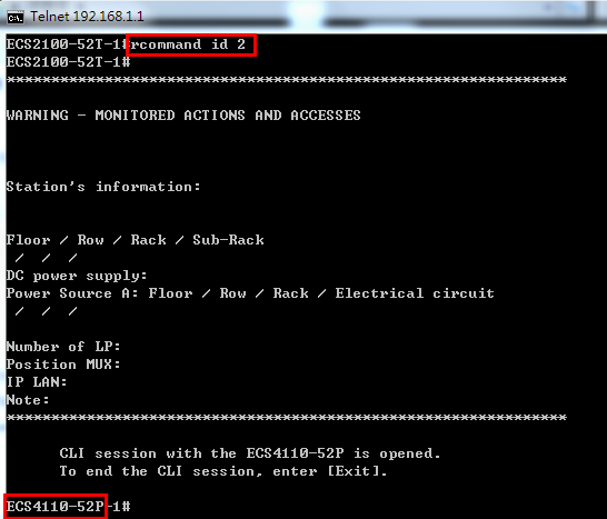
Test via web:
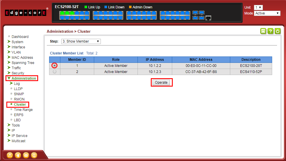
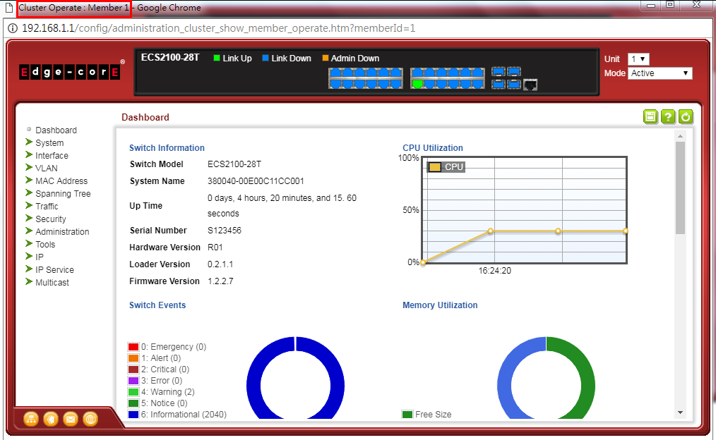
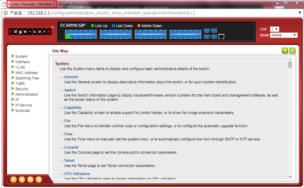
Test via console:
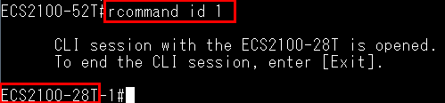
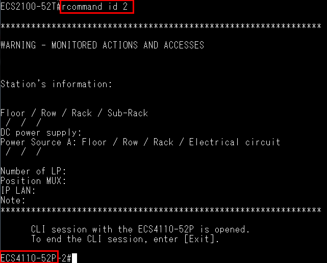
Scenario:
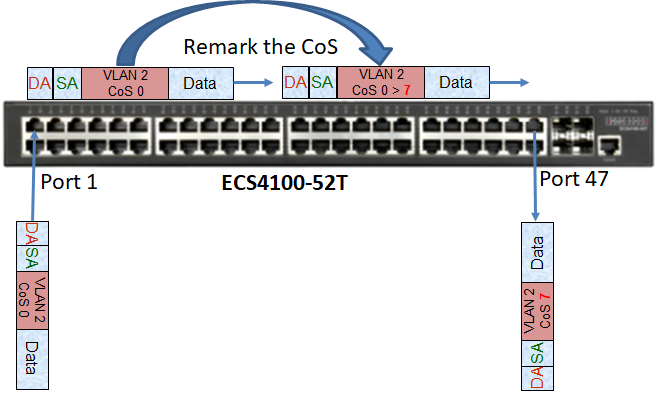
Procedures:
- Add the VID (VLAN ID) to the port interface. In this example, the traffic will tag VLAN 2.
Console#configure
Console(config)#interface ethernet 1/1
Console(config-if)#switchport allowed vlan add 2 tagged
Console(config-if)#exi
Console(config)#interface ethernet 1/47
Console(config-if)#switchport allowed vlan add 2 tagged
- Create a class map to classify the specified traffic. In this example, it will match to the traffic of CoS 0.
Console(config)#class-map CoS
Console(config-cmap)#match cos 0
Console#show class-map
Class Map match-any CoS
Description:
Match CoS 0
- Create a policy map and use the class command to configure policies for traffic which match the criteria defined in a class map. In this example, the value of CoS will be modified to “7” if the traffic match to the class map.
Console(config)#policy-map CoS-test
Console(config-pmap)#class CoS
Console(config-pmap-c)#set cos 7
Console#show policy-map
Policy Map CoS-test
Description:
class CoS
set CoS 7
- Apply the policy map to the ingress or egress side of a particular interface. In this example, the policy map will be applied to ingress of port 1.
Console#configure
Console(config)#interface ethernet 1/1
Console(config-if)#service-policy ?
input Input direction
output Output direction
Console(config-if)#service-policy input CoS-test
Console#show running-config interface ethernet 1/1
interface ethernet 1/1
switchport allowed vlan add 2 tagged
service-policy input CoS-test
!
Result:
When the switch received the packet of CoS “0” from port 1, this CoS will be modified to “7” then be sent out from the port 47.
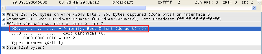
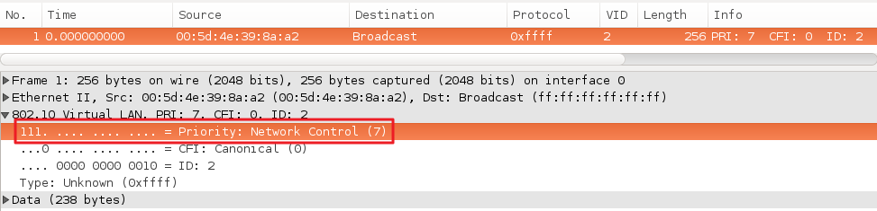
Models: ECS4620 series, ECS4510 series, ECS4120 series, ECS4100 series, ECS4110 series, ECS3510-28T/52T, ES3528MV2, ES3510MA
According to the RFC4649, the format of the DHCPv6 Relay Agent Remote-ID option show as below:
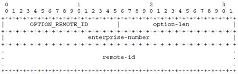
Enable DHCPv6 snooping remote-id option on switch, and capture a packet as example below.
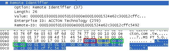
1) Correspond to the format of the DHCPv6 Relay Agent Remote-ID option.
| option-code | 00 25 |
| option-length | 00 1a |
| enterprise-number | 00 00 01 03 |
| remote-id value | 00 01 00 05 01 03 00 0e 00 01 00 01 52 4e 62 c3 00 12 cf fc 54 92 |
2)
| remote-id value | 00 01 00 05 01 03 00 0e 00 01 00 01 52 4e 62 c3 00 12 cf fc 54 92 |
| remote-id type | 00 01 |
| VLAN ID | 00 05 |
| Unit | 01 |
| Port | 03 |
| Length of DUID | 00 0e |
| DUID | 00 01 00 01 52 4e 62 c3 00 12 cf fc 54 92 |
3) There are four different definition for DUID (DHCP Unique Identifier) as below, the first one is used on Edgecore switches.
1. Link-layer address plus time (DUID-LLT) – RFC3315
2. Vendor-assigned unique ID based on Enterprise Number (DUID-EN) – RFC3315
3. Link-layer address (DUID-LL) – RFC3315
4. UUID-Based DUID (DUID-UUID) – RFC6355
※1. Link-layer address plus time (DUID-LLT) – RFC3315
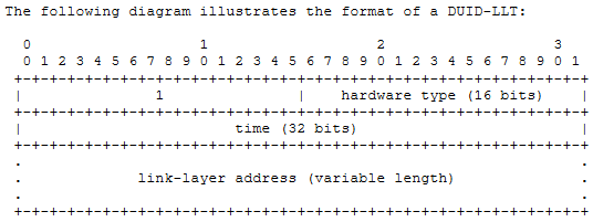
Support models:
ECS4620 series, Version: 1.2.2.34
ECS4510 series, Version: 1.5.2.34
ECS4120 series, Version: 1.0.2.33
ECS4100 series, Version: 1.2.4.173
ECS4110 series, Version: 1.2.3.12
ECS4210 series, Version: 1.0.0.56
ECS3500 series, Version: 1.5.2.8
ECS2100 series, Version: 1.2.2.9
Introduction:
Users with privilege 0~14 is not allowed to execute all commands on Edgecore switches.
The picture as shown below is the default setting for privilege level 2.
User with privilege level 2 is not allowed to enter configure mode (command “configure”).
P.S There is no configure command.
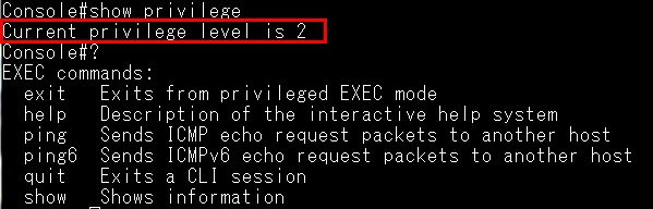
Solution:
We’re able to assign specific commands for those users with privilege 0~14 by command “privilege”.
Example:
ECS4620 series, Version: 1.2.2.34
User who belongs privilege level 2 is capable of shutdown the port and configure the IP address.
Before configuration, you have to know how many commands you need for setting.
For example:
- Exec mode: configure
- Configure mode: interface ethernet 1/1
- Configure mode: interface vlan 1
- Interface-eth mode: shutdown
- Interface-vlan mode: ip address
Configuration:
Step 1: Assign “configure” command to level 2
privilege exec level 2 configure
Step 2: Assign “interface ethernet & interface vlan” command to level 2.
privilege configure level 2 interface
privilege configure level 2 interface Ethernet
privilege configure level 2 interface vlan
Step 3: Assign “shutdown” command to level 2.
privilege interface-eth level 2 shutdown
Step 4: Assign “ip address” command to level 2.
privilege interface-vlan level 2 ip address
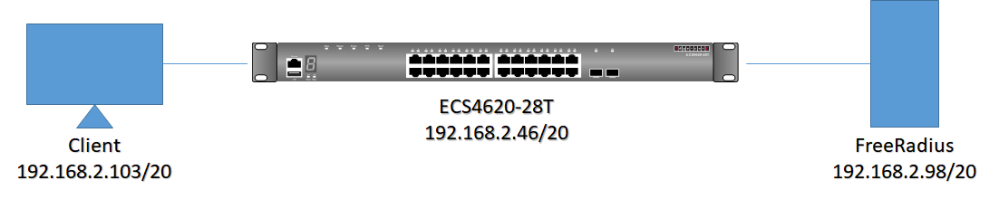
Step:
- Setup FreeRadius Server
- Configure client
- Configure switch
- Verify
- Setup FreeRadius Server
- Install freeradius server to Ubuntu((Ubuntu 14.04) as follow command:
FreeRadius ~ # apt-get install freeradius -y - Configure “users” and “clients.conf” file
Users (path: /etc/freeradius/users)
- Username “tsCommonName”. It must be as same as commonName in the client.cnf (refer to step 3)
- “Tunnel-Private-Group-ID” parameter is for dynamically adding VLAN
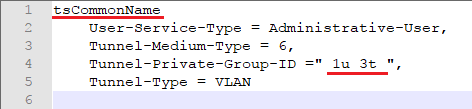
Clients.conf (path: /etc/freeradius/clients.conf)
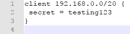
- Download the FreeRadius source code from https://freeradius.org/
After decompress the source file, use files “~/freeradius-server-3.0.15/raddb/certs” to replace “/etc/freeradius/certs”
Reference commands:
FreeRadius certs # pwd
/etc/freeradius/certs
FreeRadius certs # rm -rf *
FreeRadius certs # cp -Rf ~/freeradius-server-3.0.15/raddb/certs/* .
- Modify ca files: server.cnf / client.cnf
server.cnf: modify output_password (path: /etc/freeradius/certs/server.cnf)
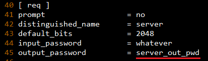
client.cnf: modify output_password, emailAddress and commonName
(path: /etc/freeradius/certs/client.cnf )
- commonName need same as “Username” in users file
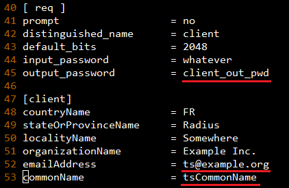
- Launch bootstrap script (path: /etc/freeradius/certs/bootstrap )
FreeRadius certs # ./bootstrap - Copy “ca.pem”, “client.key” and “[email protected]” (which is as same as “emailAddress” parameter) to Client.
/etc/freeradius/certs/ca.pem
/etc/freeradius/certs/client.key
/etc/freeradius/certs/[email protected]
- Modify eap.conf file (path: /etc/freeradius/eap.conf)
- Change default_eap_type to tls

- Remove(delete or comment) the make_cert_command

- Change “private_key_password” value as same as server.cnf’s output_password.

- After all Server side configuration is finished, restart the FreeRadius server.
- FreeRadius freeradius # Service freeradius start => start server normally or
- FreeRadius freeradius # Freeradius -X => start server with debug mode.
- Configure client
- Get the three files at configure server, please refer to “Setup FreeRadius Server” step 5
2. Add CA to client and update CA
Commands:
root@ts:/home/ts/Desktop# cp ca.pem /usr/local/share/ca-certificates/ca.pem.crt
root@ts:/home/ts/Desktop# update-ca-certificates
- Configure Client’s network configure
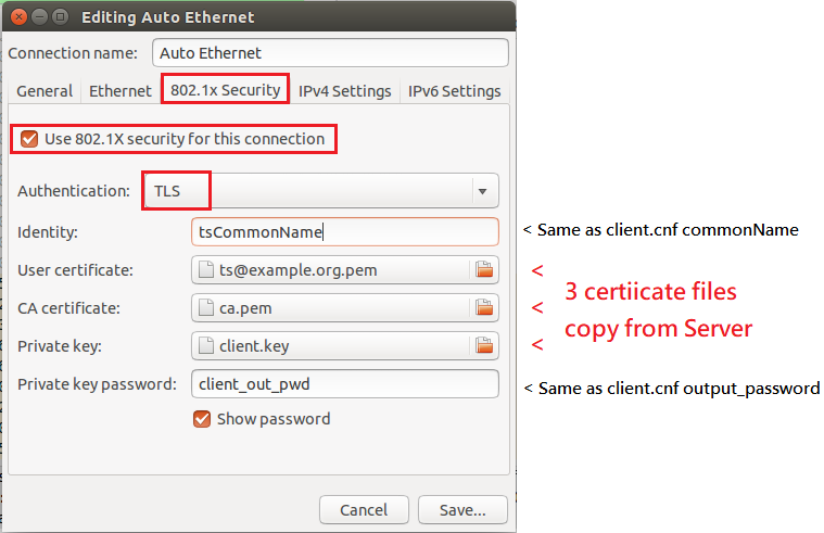
- Configure switch
- Switch IP:
Console#configure
Console(config)#interface vlan 1
Console(config-if)#ip address 192.168.2.46/20
- Switch Vlan:
Console(config)#vlan database
Console(config-vlan)#vlan 3
Global Configuration:
Console(config)#dot1x system-auth-control
Interface Configuration:
Console(config)#interface eth 1/3
Console(config-if)#dot1x port-control auto
- Verify
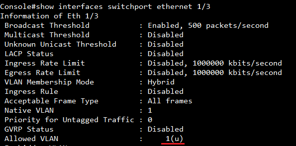
After authentication, port #3 allows the traffic which belong to vlan 1(u) and 3(t)
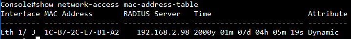
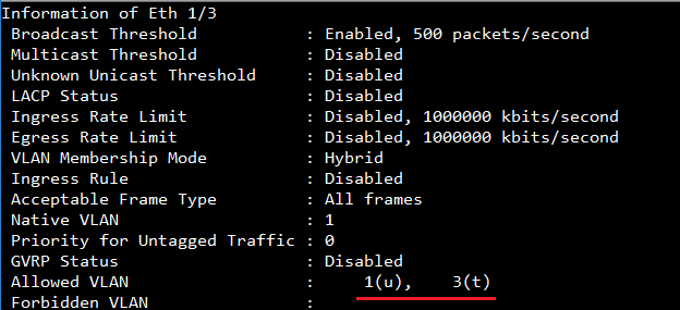
In show vlan, you can see port #3 dynamic add to vlan 3
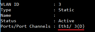
Scenario:
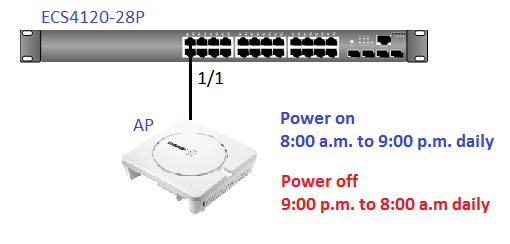
Configuration on ECS4120-28P:
Example for periodic time and date
ECS4120-28P#con
ECS4120-28P(config)#time-range TEST
ECS4120-28P(config-time-range)#periodic daily 8 0 to daily 21 0
ECS4120-28P(config-time-range)#exit
ECS4120-28P(config)#interface ethernet 1/1
ECS4120-28P(config-if)#power inline time-range TEST
ECS4120-28P(config-if)#end
ECS4120-28P#
[CLI Command]
time-range name
periodic
{daily | friday | monday | saturday | sunday | thursday | tuesday | wednesday | weekdays | weekend} hour minute
to
{daily | friday | monday | saturday | sunday | thursday | tuesday | wednesday | weekdays | weekend } hour minute
[SNMPSET command format]
1. Enable time-range
snmpset -v 2c -c private {switch ip} {timeRangeStatus}.{timeRangeIndex} {integer} {value}
For timeRangeStatus, OID 1.3.6.1.4.1.259.10.1.45.1.61.1.1.3
Set OID 1.3.6.1.4.1.259.10.1.45.1.61.1.1.3 to valid(1) to create an entry.
Set OID 1.3.6.1.4.1.259.10.1.45.1.61.1.1.3 to invalid(2) to destroy an entry.
For timeRangeIndex: The index for time-range
Identified starts from 0.
2. Create time-range
snmpset -v 2c -c private {switch ip} {timeRangeName}.{timeRangeIndex} {string} {name}
For timeRangeName, OID 1.3.6.1.4.1.259.10.1.45.1.61.1.1.2
Configure as string, user should give a name to the time-range.
3. Configure time range rule
snmpset -v 2c -c private {switch ip} {timeRangePeriodic}.{timeRangeIndex}.{PeriodicType}.{startHour}.{startMinute}.{PeriodicType}.{endHour}.{endMinute}
{integer} {value}
For timeRangePeriodic, OID 1.3.6.1.4.1.259.10.1.45.1.61.2.1.8
Set OID 1.3.6.1.4.1.259.10.1.45.1.61.2.1.8 to valid(1) to create an entry and periodic execute.
Set OID 1.3.6.1.4.1.259.10.1.45.1.61.2.1.8to invalid(2) to destroy an entry.
For PeriodicType, {sunday(0),monday(1),tuesday(2),wednesday(3),thursday(4),friday(5),saturday(6),daily(7),weekdays(8),weekend(9)}
For startHour and startMinute: Integer.
For endHour and endMinute: Integer.
4. Assign time-range to power inline
snmpset -v 2c -c private {switch ip} {PSE_Port_TimeRange_Name}.{UnitID}.{PortID} {string} {TimeRange_Name}
For PSE_Port_TimeRange_Name, OID 1.3.6.1.4.1.259.10.1.45.1.28.6.1.11
Configure as string, user should assign a specific time-range.
For UnitID and PortID,
Specify the port that apply the time-range.
Example for configure via SNMP:
(1) timeRangeStatus, OID 1.3.6.1.4.1.259.10.1.45.1.61.1.1.3 ; timeRangeIndex = 0 (Integer 1 : valid)

(2) timeRangeName, OID 1.3.6.1.4.1.259.10.1.45.1.61.1.1.2 ; timeRangeIndex = 0 (String “TEST”: the profile name is TEST)

(3) timeRangePeriodic, OID 1.3.6.1.4.1.259.10.1.45.1.61.2.1.8 ; timeRangeIndex = 0 ; PeriodicType = daily(7) ;
startHour = 8 ; startMinute = 0 ; PeriodicType = daily(7) ; endHour = 21 ; endMinute = 0 (Integer 1 : valid)
 (4) PSE_Port_TimeRange_Name, OID 1.3.6.1.4.1.259.10.1.45.1.28.6.1.11 ; UnitID = 1 ; PortID = 1
(String “TEST”: Apply the profile TEST)

Result:
Time range table in ECS4120-28P.
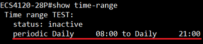
When the system is operating in the time-range (8:00 to 21:00), AP will power on.

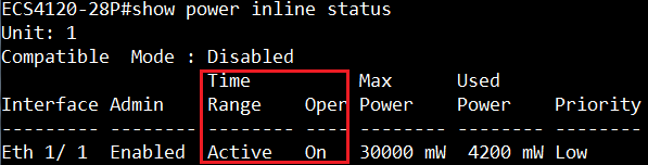
.png)
When the system is out of the time-range, PSE will not supply the power.

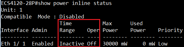
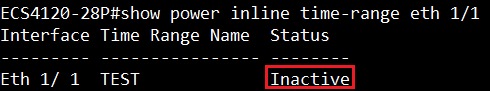
Model:
ECS4100 series
Firmware version:
ECS4100 series V1.2.4.173
Simulation scenario:
- Prepare two types of ARP packets.
A. The sender MAC address of ARP header is different from source MAC address of Ethernet header.
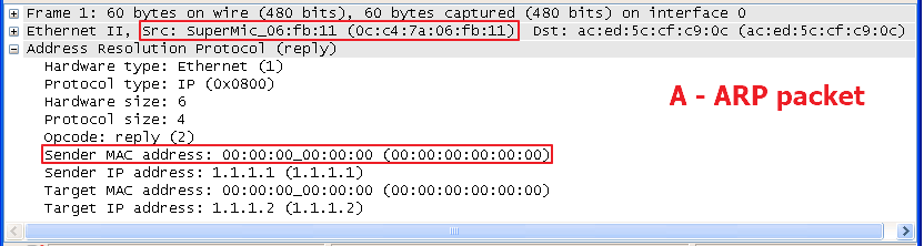
B. The sender MAC address of ARP header is the same as source MAC address of Ethernet header.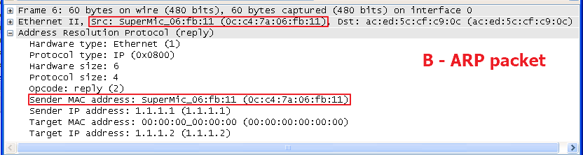
- Configure MAC ACL to permit the source MAC address of ARP packet and deny other packets.
Console(config)#access-list mac test
Console(config-mac-acl)#permit host 0C-C4-7A-06-FB-11 any
Console(config-mac-acl)#deny any any
- Apply this MAC ACL to ingress of port 1.
Console(config)#interface ethernet 1/1
Console(config-if)#mac access-group test in
- Inject these two ARP packets to the port 1. Thus, the switch forwards B-ARP packet but filter A-ARP packet by MAC ACL.
This is chipset behavior. MAC ACL inspect sender MAC address of ARP header instead of source MAC address of Ethernet header for ARP packets.
Support models:
ECS4620 series, Version: 1.2.2.34
ECS4510 series, Version: 1.5.2.34
ECS4120 series, Version: 1.0.2.33
ECS4100 series, Version: 1.2.4.173
ECS4110 series, Version: 1.2.3.12
ECS3500 series, Version: 1.5.2.8
Here’s the sample: (use ECS4620-28F)
Topology:
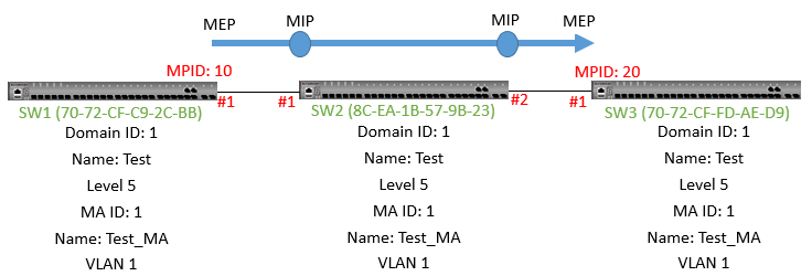
Maintenance End Point (MEP): generates and responds to CFM PDUs
Maintenance Intermediate Points (MIP): Forwarding CFM PDUs as intermediate maintenance points
SW1 configuration:
SW1#con
SW1(config)#ethernet cfm domain index 1 name Test level 5
(create maintenance domain [MD], the index is 1, name is character string “Test”, the MD level 5)
SW1(config-ether-cfm)#ma index 1 name Test_MA vlan 1
(create maintenance association [MA] service in MD, the index is 2, name is “Test_MA” and service VLAN identifier is “1.”)
SW1(config-ether-cfm)#mep crosscheck mpid 20 ma Test_MA
(Configure MEP crosscheck with mpid 20 on SW 3 ma “Test_MA.” The Cross Check List for a MD contains a list of MEPID (Maintenance End Point Identifier) which are configured in a MA)
SW1(config-ether-cfm)#exit
SW1(config)#interface ethernet 1/1
SW1(config-if)#ethernet cfm mep mpid 10 md Test ma Test_MA
(Create mep mpid 10 on port 1)
SW2 configuration:
SW2#con
SW2(config)#ethernet cfm domain index 1 name Test level 5
SW2(config-ether-cfm)#ma index 1 name Test_MA vlan 1
SW2(config-ether-cfm)#end
SW3 configuration:
SW3#con
SW3(config)#ethernet cfm domain index 1 name Test level 5
SW3(config-ether-cfm)#ma index 1 name Test_MA vlan 1
SW3(config-ether-cfm)#mep crosscheck mpid 10 ma Test_MA
SW3(config-ether-cfm)#exit
SW3(config)#interface ethernet 1/1
SW3(config-if)#ethernet cfm mep mpid 20 md Test ma Test_MA
The Link trace SW1 port1 to SW3 port 1.
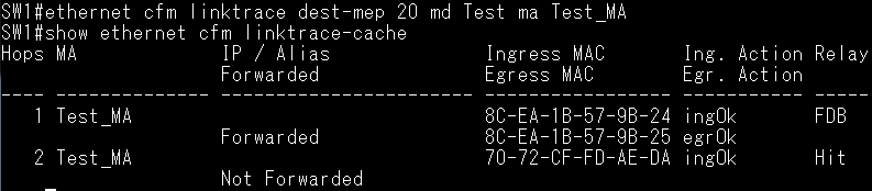
The MAC listed as below are the port MAC
8C-EA-1B-57-9B-24 (SW2 port 1/1 MAC)
8C-EA-1b-57-9B-25 (SW2 port 1/2 MAC)
70-72-CF-FD-AE-DA (SW3 port 1/1 MAC)
- Topology
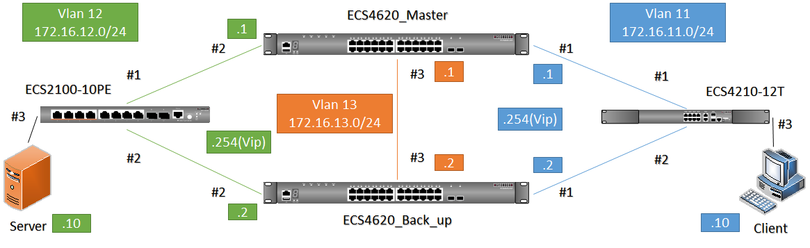
- VRRP Master(ECS4620_Master) configuration:
- Basic configuration (detail configuration please refer to Appendix)
- Create VLAN 11-13
- Configure VLAN IP address
- Set each port allow VLAN
Port #2: PVID = 12, VID = 12(u)
Port #3: PVID = 13, VID = 13(u)
- Disable Spanning-tree on downlink port(#1, #2)
- Set default route to VLAN 13
- VRRP configuration(virtual IP addresses for VLAN 11 and VLAN 12)
Master(config)#interface vlan 11
Master(config-if)#vrrp 1 ip 172.16.11.254
Master(config-if)#vrrp 1 priority 200
Master(config-if)#interface vlan 12
Master(config-if)#vrrp 2 ip 172.16.12.254
Master(config-if)#vrrp 2 priority 200
- VRRP Backup(ECS4620_Back_up) configuration
- Basic configuration (detail configuration please refer to Appendix)
- Create VLAN 11-13
- Configure VLAN IP address
- Set each ports’ allow VLAN
Port #2: PVID = 12, VID = 12(u)
Port #3: PVID = 13, VID = 13(u)
- Disable Spanning-tree at downlink port(#1, #2)
- Set default route to VLAN 13
- VRRP configuration(virtual IP addresses for VLAN 11 and VLAN 12)
BackUp(config-if)#vrrp 1 ip 172.16.11.254
BackUp(config-if)#interface vlan 12
BackUp(config-if)#vrrp 2 ip 172.16.12.254
- Check VRRP status on VRRP Master and Backup
- Show VRRP [ID]
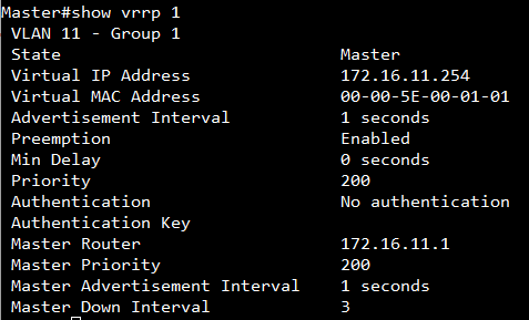
- Show VRRP brief
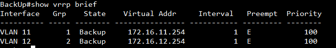
- Server/Client configure
| Server Side | Client Side |
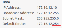 |
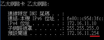 |
When server or client sends packet to gateway, the format of destination MAC address is 00-00-5E-00-01-[VRRP-ID]
Client send packet
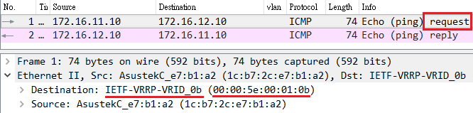
Server send packet
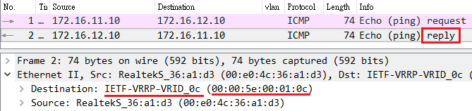
Appendix
Details of VRRP Master(ECS4620_Master) configuration:
- Basic configure
Master#configure
Master(config)#vlan database
Master(config-vlan)#vlan 11-13
Configure VLAN IP address
Master#configure
Master(config)#interface vlan 11
Master(config-if)#ip address 172.16.11.1/24
Master(config-if)#interface vlan 12
Master(config-if)#ip address 172.16.12.1/24
Master(config-if)#interface vlan 13
Master(config-if)#ip address 172.16.13.1/24
2. Set each port allow VLAN
Master#configure
Master(config)#interface ethernet 1/1
Master(config-if)#switchport allowed vlan add 11 untagged
Master(config-if)#switchport native vlan 11
Master(config-if)#switchport allowed vlan remove 1
Master(config-if)#interface ethernet 1/2
Master(config-if)#switchport allowed vlan add 12 untagged
Master(config-if)#switchport native vlan 12
Master(config-if)#switchport allowed vlan remove 1
Master(config-if)#interface ethernet 1/3
Master(config-if)#switchport allowed vlan add 13 untagged
Master(config-if)#switchport native vlan 13
Master(config-if)#switchport allowed vlan remove 1
3. Disable Spanning-tree at downlink port(#1, #2)
Master#configure
Master(config)#interface ethernet 1/1
Master(config-if)#spanning-tree spanning-disabled
Master(config-if)#interface ethernet 1/2
Master(config-if)#spanning-tree spanning-disabled
4. Set default route to vlan 13
Master#configure
Master(config)#ip default-gateway 172.16.13.2
Details of VRRP Backup (ECS4620_Back_up) configuration
- Basic configure
- Create VLAN 11-13
BackUp (config)#vlan database
BackUp(config-vlan)#vlan 11-13
2. Configure VLAN IP address
BackUp#configure
BackUp(config)#interface vlan 11
BackUp(config-if)#ip address 172.16.11.2/24
BackUp(config-if)#interface vlan 12
BackUp(config-if)#ip address 172.16.12.2/24
BackUp(config-if)#interface vlan 13
BackUp(config-if)#ip address 172.16.13.2/24
3. Set each port allow vlan
BackUp#configure
BackUp(config)#interface ethernet 1/1
BackUp(config-if)#switchport allowed vlan add 11 untagged
BackUp(config-if)#switchport native vlan 11
BackUp(config-if)#switchport allowed vlan remove 1
BackUp(config-if)#interface ethernet 1/2
BackUp(config-if)#switchport allowed vlan add 12 untagged
BackUp(config-if)#switchport native vlan 12
BackUp(config-if)#switchport allowed vlan remove 1
BackUp(config-if)#interface ethernet 1/3
BackUp(config-if)#switchport allowed vlan add 13 untagged
BackUp(config-if)#switchport native vlan 13
BackUp(config-if)#switchport allowed vlan remove 1
4.Disable Spanning-tree at downlink port(#1, #2)
BackUp#configure
BackUp(config)#interface ethernet 1/1
BackUp(config-if)#spanning-tree spanning-disabled
BackUp(config-if)#interface ethernet 1/2
BackUp(config-if)#spanning-tree spanning-disabled
- Set default route to vlan 13
BackUp (config)#ip default-gateway 172.16.13.1
Scenario:
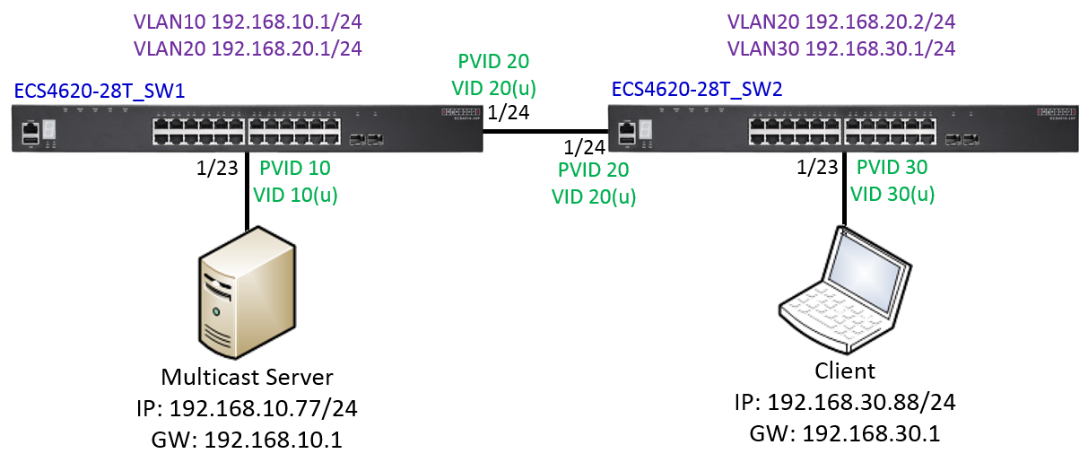
Configuration on ECS4620-28T_SW1:
SW1#con
SW1(config)#interface ethernet 1/23
SW1(config-if)#switchport allowed vlan add 10 untagged
SW1(config-if)#switchport native vlan 10
SW1(config-if)#switchport allowed vlan remove 1
SW1(config-if)#exit
SW1(config)#interface ethernet 1/24
SW1(config-if)#switchport allowed vlan add 20 untagged
SW1(config-if)#switchport native vlan 20
SW1(config-if)#switchport allowed vlan remove 1
SW1(config-if)#exit
SW1(config)#interface vlan 10
SW1(config-if)#ip address 192.168.10.1/24
SW1(config-if)#ip igmp
SW1(config-if)#ip pim sparse-mode
SW1(config-if)#exit
SW1(config)#interface vlan 20
SW1(config-if)#ip address 192.168.20.1/24
SW1(config-if)#ip igmp
SW1(config-if)#ip pim sparse-mode
SW1(config-if)#exit
SW1(config)#ip multicast-routing
SW1(config)#router pim
SW1(config)#ip pim rp-address 192.168.10.1
SW1(config)#router ospf
SW1(config-router)#network 192.168.10.0 255.255.255.0 area 0
SW1(config-router)#network 192.168.20.0 255.255.255.0 area 0
SW1(config-router)#end
Configuration on ECS4620-28T_SW2:
SW2#con
SW2(config)#interface ethernet 1/23
SW2(config-if)#switchport allowed vlan add 30 untagged
SW2(config-if)#switchport native vlan 30
SW2(config-if)#switchport allowed vlan remove 1
SW2(config-if)#exit
SW2(config)#interface ethernet 1/24
SW2(config-if)#switchport allowed vlan add 20 untagged
SW2(config-if)#switchport native vlan 20
SW2(config-if)#switchport allowed vlan remove 1
SW2(config-if)#exit
SW2(config)#interface vlan 20
SW2(config-if)#ip address 192.168.20.2/24
SW2(config-if)#ip igmp
SW2(config-if)#ip pim sparse-mode
SW2(config-if)#exit
SW2(config)#interface vlan 30
SW2(config-if)#ip address 192.168.30.1/24
SW2(config-if)#ip igmp
SW2(config-if)#ip pim sparse-mode
SW2(config-if)#exit
SW2(config)#ip multicast-routing
SW2(config)#router pim
SW2(config)#ip pim rp-address 192.168.10.1
SW2(config)#router ospf
SW2(config-router)#network 192.168.20.0 255.255.255.0 area 0
SW2(config-router)#network 192.168.30.0 255.255.255.0 area 0
SW2(config-router)#end
Display the information about interfaces configured for PIM.

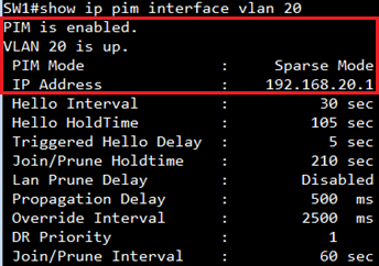
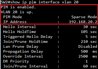
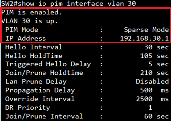
Display the multicast information for the specified interface.
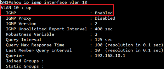
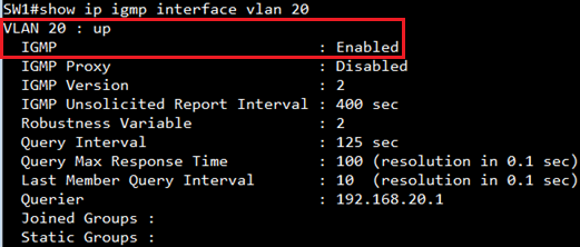
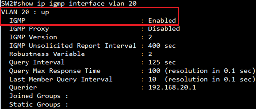

Display the information in the routing table.
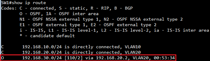
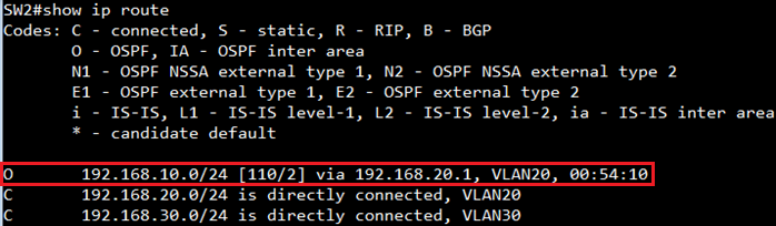
Display the information about PIM neighbors.
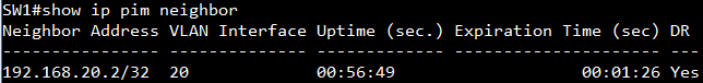
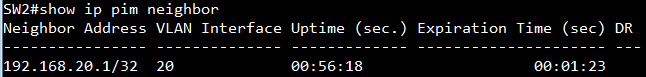
Display the active RPs and associated multicast routing entries.
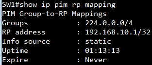
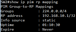
Display the information for IGMP groups.
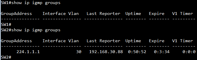
Display the IPv4 multicast routing table.
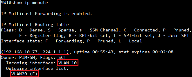
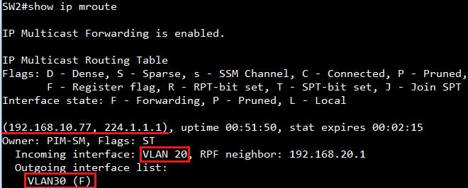
The basic MVR topology and configuration on the switches as below.

Original Behavior: (Not support “transmit-filter” command or “transmit-filter” disabled.)
When the switch enabled MVR function and the status becomes "Active", once the client joins/leaves the multicast group by sending out the report to MVR receiver port.
This report will be forwarded to All the Active Source ports as below.
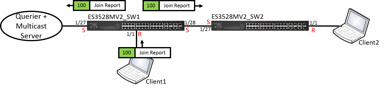
The MVR member of ES3528MV2_SW1 and ES3528MV2_SW2 as below.
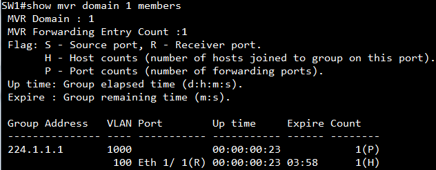
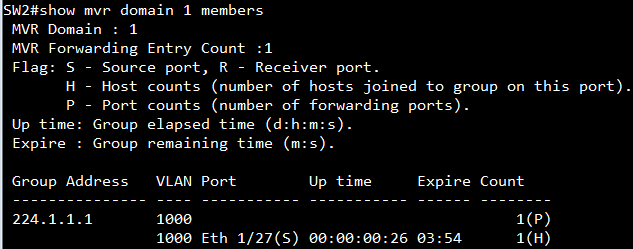
Enabled Transmit-Filter Behavior: (Transmit-filter is disabled on switch by default.)
The mechanism is the same, but this report will not be forwarded to the port which enable transmit-filter as below.
The user could easily configure how the report forward on MVR source ports.
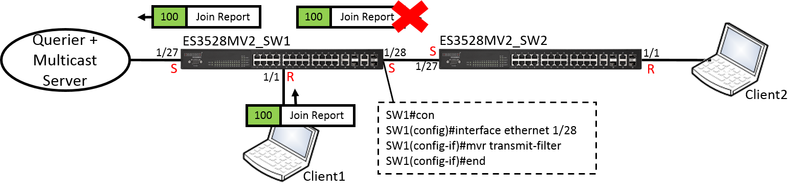
The MVR member of ES3528MV2_SW1 and ES3528MV2_SW2 as below.
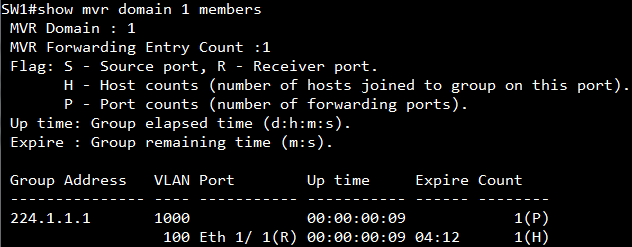
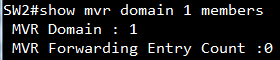
Display transmit-filter per port configuration.

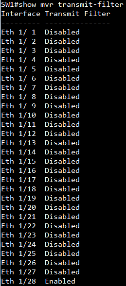
Support models and software version:
ECS4210 series v1.0.0.61
ES3528MV2 v1.5.2.14
ECS3510-28T/52T v1.5.2.14
ES3510MA v1.5.2.14
[SNMPSET command format]
snmpwalk -v 2c -c private {switch ip} { amtrMacAddrDynamicCount | amtrMacAddrStaticCount | amtrMacAddrTotalCount }
For amtrMacAddrDynamicCount, OID 1.3.6.1.4.1.259.10.1.43.1.1.8.4
The number of dot1dTpFdbTable entries in the BRIDGE-MIB.
For amtrMacAddrStaticCount, OID 1.3.6.1.4.1.259.10.1.43.1.1.8.5
The number of dot1dStaticTable entries in the BRIDGE-MIB.
For amtrMacAddrTotalCount, OID 1.3.6.1.4.1.259.10.1.43.1.1.8.6
The sum of dot1dTpFdbTable and dot1dStaticTable entries.
For example, the following are current mac-address table entries and mac-address count display by CLI command.
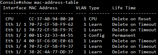
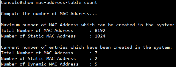
The following are the number of Dynamic/Static/Total MAC address count display by SNMP.
(1) amtrMacAddrDynamicCount, OID 1.3.6.1.4.1.259.10.1.43.1.1.8.4
Number of Dynamic MAC Address : 5

(2) amtrMacAddrStaticCount, OID 1.3.6.1.4.1.259.10.1.43.1.1.8.5
Number of Static MAC Address : 2

(3) amtrMacAddrTotalCount, OID 1.3.6.1.4.1.259.10.1.43.1.1.8.6
Total Number of MAC Address : 7

Support Model Name: ECS4620 series
Software Version: v1.2.2.39
If enable network-access aging then the switch's secure MAC address table will be removed when the aging time expires or detect the MAC address on new ports.
So we enhance Sticky MAC function on ECS4620 series. When you connect the interface to your network, you can enable the sticky MAC feature and ensure that MAC-address is only learned on this port and protect MAC-address is not learned by other ports even port move or any attack.
Topology:
- Port 1 enable sticky MAC, and connect a PC on it. The PC's MAC address was learned on port 1.
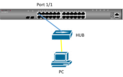
- Disconnect the PC’s link which connect to the hub, and move to port 2. Then the PC will fail to access the network through the port2 due to the MAC address was already learned on port1.
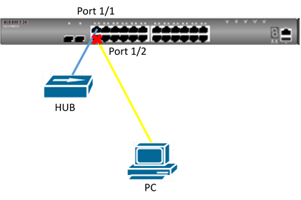
Procedure:
Step1:
Enable port security and sticky MAC on port 1.
Enable network-access aging on global.
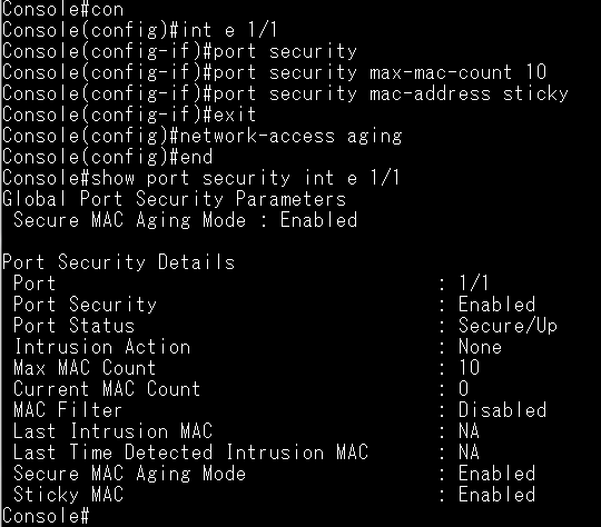
Step2:
Connect the PC to port 1. And check the MAC address was learned on port 1
.png)
Step3:
Disconnect the PC's link which connect to the hub, and move to port 2
Confirm the PC's MAC address still be learned on port 1, and fail to learn on port 2.
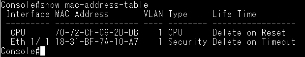
Step 4:
Port 2 enable port security and set intrusion action as shutdown.
(Suggest set max-mac-count > 1)
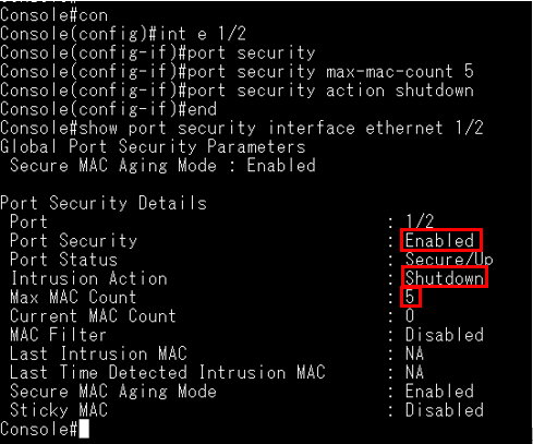
Disconnect the PC’s link which connect to the hub, and move to port 2.
Confirm the port is shut down by the sticky secure MAC address intrude into other port security enabled port.
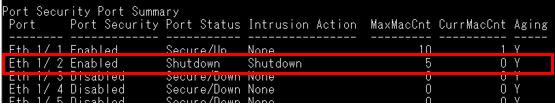
Support models: ECS4100 series
Scenario:
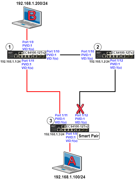
Concept:
CLI Configuration:
Step 1) Disable spanning-tree on each port
Dut1:
Dut1#configure
Dut1(config)#interface ethernet 1/9,10,11
Dut1(config-if)#spanning-tree spanning-disabled
Dut2:
Dut2#configure
Dut2(config)#interface ethernet 1/10,12
Dut2(config-if)#spanning-tree spanning-disabled
Dut3:
Dut3#configure
Dut3(config)#interface ethernet 1/9,11,12
Dut3(config-if)#spanning-tree spanning-disabled
*Note: Smart Pair can’t be configured as one of these port types.
- LACP enable port
- Spanning Tree enabled port
Step 2) Set the smart pair configuration on Dut3
Dut3:
Dut3#configure
Dut3(config)#smart-pair 1
Dut3(config-smart-pair)#primary-port ethernet 1/11
Dut3(config-smart-pair)#backup-port ethernet 1/12
Step 3) Check the smart pair configuration is correct
Dut3:
Dut3#show smart-pair 1
Primary Port : Eth 1/11 (forwarding)
Backup Port : Eth 1/12 (blocking)
Wait-To-Restore Delay : 30 seconds
*Default WTR time is 30 seconds
Step 4) Client A keep pinging Clint B
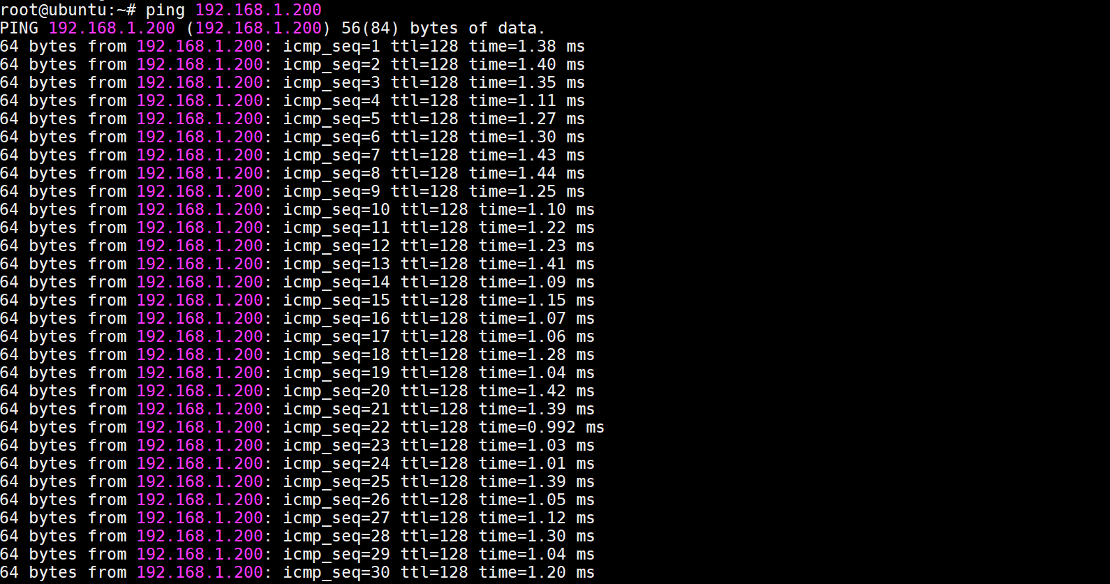
The traffic is normal
Step 5) Client A keep pinging Clint B and then unplug Dut3_Port1/11
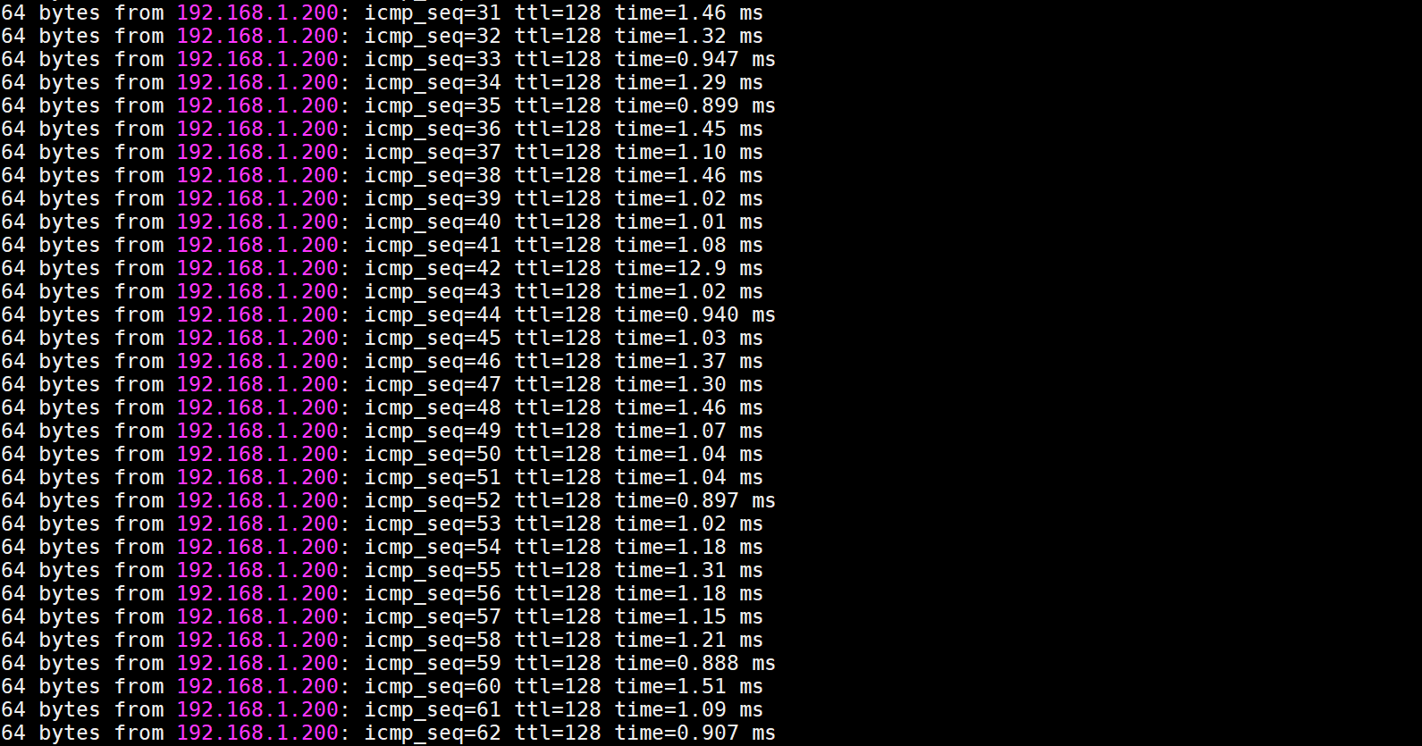
Since the traffic failover to the backup port (Port1/12), the ICMP traffic will still work.

Step 6) Check the smart pair status
Dut3:
Dut3#show smart-pair 1
Primary Port : Eth 1/11 (blocking)
Backup Port : Eth 1/12 (forwarding)
Wait-To-Restore Delay : 30 seconds
Step 7) Plug in Dut3_Port1/11 and wait for 30 seconds
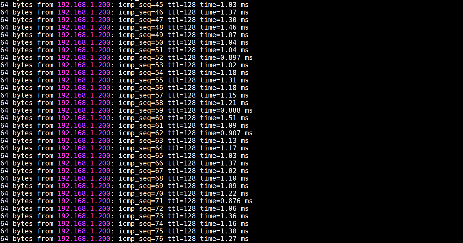
The ICMP traffic will still work when the traffic transfer back to the primary port
Step 8) Check the smart pair status
Dut3:
Dut3#show smart-pair 1
Primary Port : Eth 1/11 (forwarding)
Backup Port : Eth 1/12 (blocking)
Wait-To-Restore Delay : 30 seconds
WEB Configuration:
Step 1) Set the management IP on each switch
Dut1:
Dut1#configure
Dut1(config)#interface vlan 1
Dut1(config-if)#ip address 192.168.1.1/24
Dut2:
Dut2#configure
Dut2(config)#interface vlan 1
Dut2(config-if)#ip address 192.168.1.2/24
Dut3:
Dut3#configure
Dut3(config)#interface vlan 1
Dut3(config-if)#ip address 192.168.1.3/24
Step 1) Log in the switch by Web GUI
Dut1:
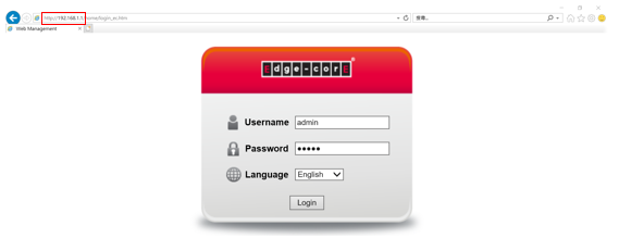
Step 2) Disable the spanning tree
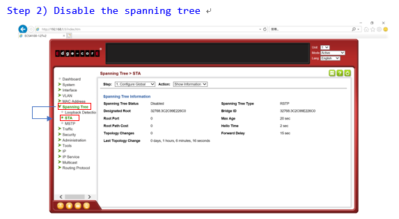
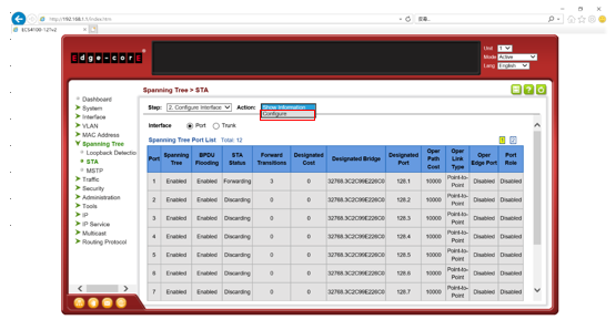 |
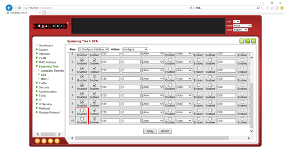
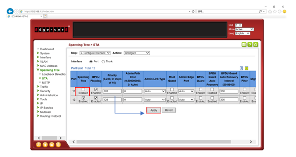
Step 3) Disable the spanning tree
Dut2: Follow the same steps as Dut1
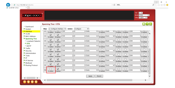 |
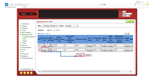
Step 4) Disable the spanning tree
Dut3: Follow the same steps as Dut1
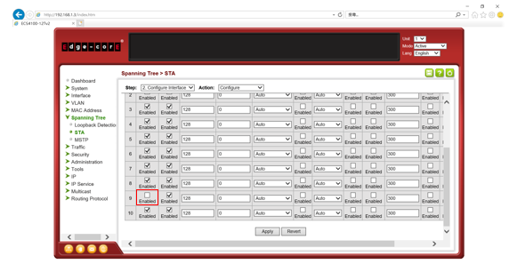
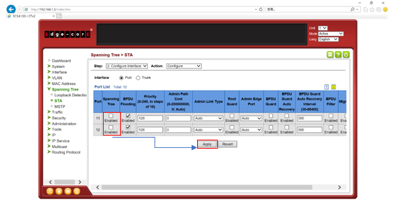
Step 5) Set the smart pair configuration on Dut3
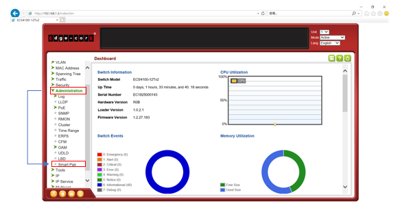
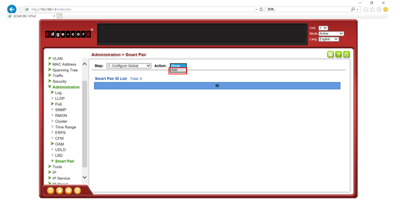
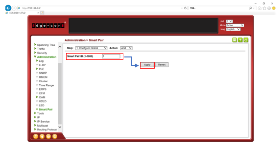
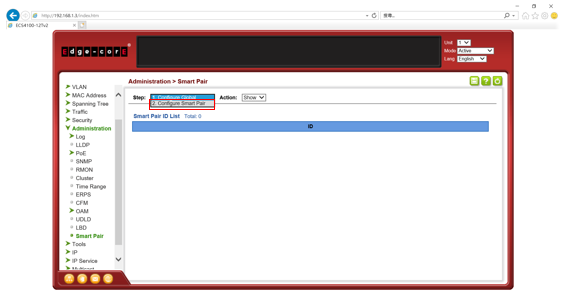
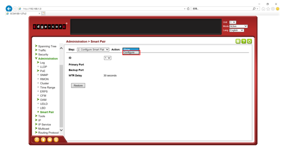
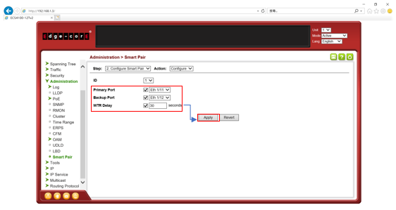
Step 6) Check the smart pair status
.png)
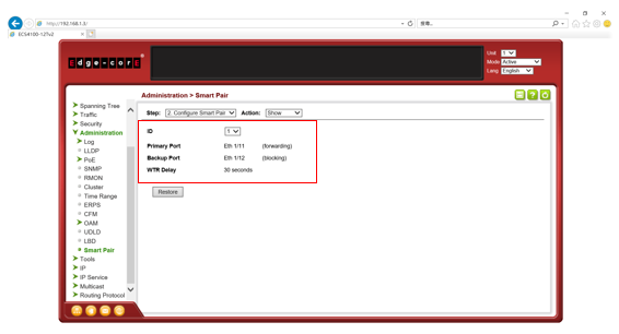
The status is normal
Client A keep pinging Clint B
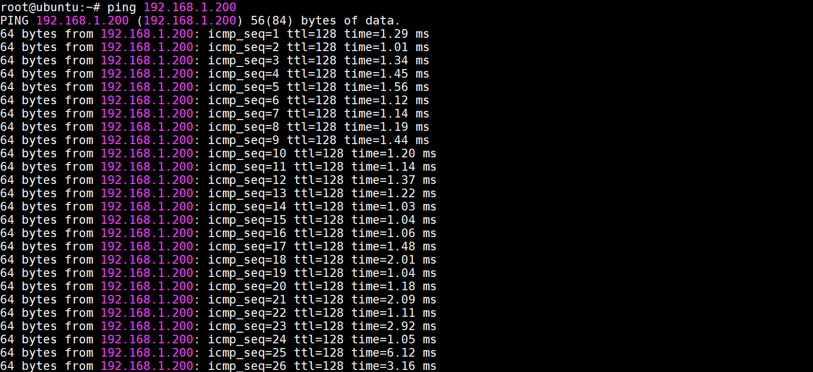
The traffic is normal
Client A keep pinging Clint B and then unplug in Dut3_Port1/11

Since the traffic failover to the backup port (Port1/12), the ICMP traffic will still work.
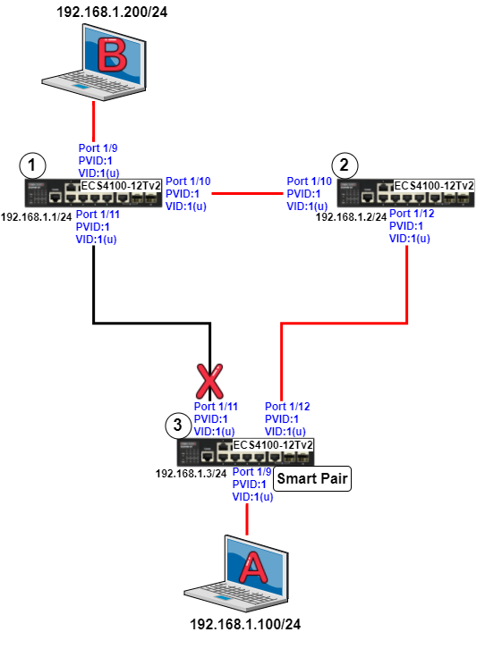
Step 9) Check the smart pair status
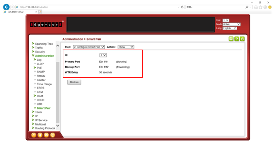
Step 10) Plug in Dut3_Port1/11 and wait for 30 seconds
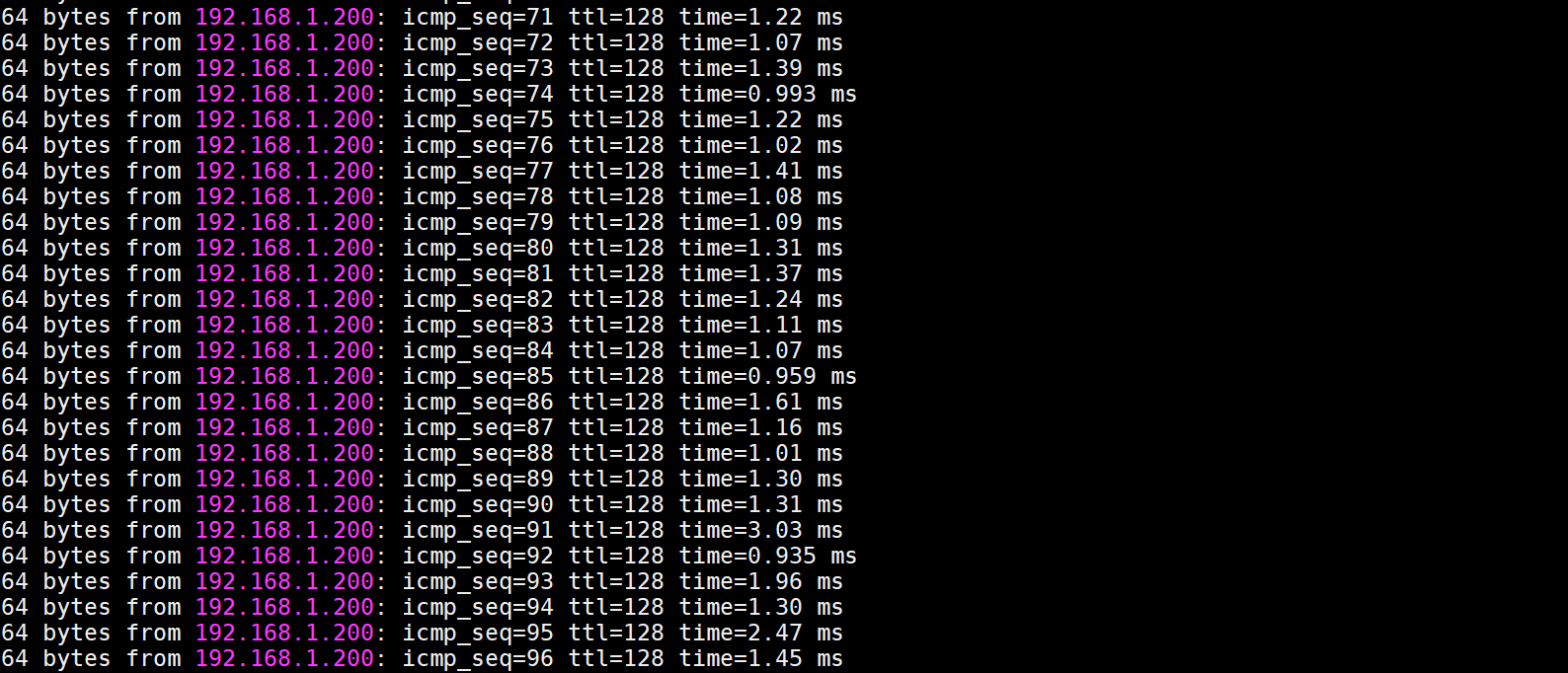
The ICMP traffic will still work when the traffic transfer back to the primary port
Step 11) Check the smart pair status
.png)
Support Model and Firmware version:
ECS4100 Series (Firmware version 1.2.30.183 and above)
ECS4120 Series (Firmware version 1.2.2.5 and above)
Summary:
| Agent settings | Length for string |
| PPPoEIA Circuit-id | 57 characters |
| PPPoEIA Remote-id | 63 characters |
| DHCPSNP option82 Circuit-id | 246 characters *1 |
| DHCPSNP option82 Remote-id | 246 characters *2 |
1.PPPoE IA - Circuit ID and Remote ID
The Access-Node MUST encode and send the Circuit ID and Remote ID as a TAG in PPPoE discoveryPacket in the format described as below:
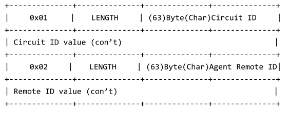
According to TR101, we append the capability of setting PPPoE IA sub-tags as following.
PPPoEIA Circuit-id string length to 57
PPPoEIA Remote-id string to 63
At the maximum length setting string with Circuit-id, the sub-tag of the packet will be
Type: 01
Length: 3f (63)
Value: node id (1 byte minimum) + "eth" (occupy 5 bytes) + string (57 bytes remain)
At the maximum length setting string with Remote-id, the sub-tag of the packet will be
Type: 02
Length: 3f (63)
Value: string (63 bytes remain)
2.DHCP Relay Agent Information Option

The length N gives the total number of octets in the Agent Information Field. The Agent Information field consists of a sequence of SubOpt/Length/Value tuples for each sub-option, encoded in the following manner:
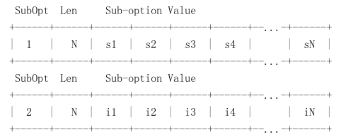
The initial assignment of DHCP Relay Agent Sub-options is as follows:
DHCP Agent Sub-Option Description
Sub-option Code
--------------- ---------------------------------
1 Agent Circuit ID Sub-option
According to RFC3046 and TR101, we append the capability of setting DHCPSNP option82 as following.
DHCPSNP option82 Circuit-id string length to 246.
DHCPSNP option82 Remote-id string to 246.
Note: DHCPSNP option82 total length is 255 bytes, both Circuit-id and Remote-id share this space.
At the max length setting string with Circuit-id while the Remote-id manually configured 1 byte string.
The space for Circuit-id string is 255-4-4-1=246 bytes.
Type: 01 (sub-option 1 circuit-id)
Length: f8 (248)
Type: 01 (string)
Length: f6 (246)
Value: string (246 bytes remain)
At the max length setting string with Remote-id while the Circuit-id manually configured 1 byte string.
The space for Remote-id string is 255-4-4-1=246 bytes
Type: 02 (sub-option 2 remote-id)
Length: f8 (248)
Type: 04 (string)
Length: f6 (246)
Value: string (246 bytes remain)
Note: When DHCPSNP option82 function enabled on an Edge-Core switch, the default setting of Circuit-id and Remote-id will have a format as following.
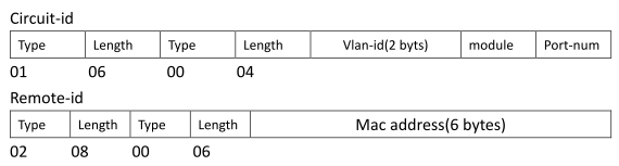
ECS2100 series firmware version v1.2.2.12 and above has a new software enhancement which support Layer 2 / Layer 3 DHCP Relay function. And the user may choose to use the L2 or L3 DHCP Relay by following commands (Default is L3).
The setting for Layer 2 DHCP Relay
Console(config)#ip dhcp l2 relay
The setting for Layer 3 DHCP Relay
Console(config)#ip dhcp l3 relay
When the client and DHCP server are in the same VLAN and subnet, the client may obtain the IP address from DHCP server directly. However, in practical network, clients might be in the different subnet and VLAN, then DHCP Relay function can help to get the IP address from DHCP server which is in the different subnet.
- L2 DHCP Relay
The L2 DHCP Relay function can be used to add the suboption information (DHCP Option 82.) and the DHCP server may refer it to assigns the corresponding IP address.
Topology:
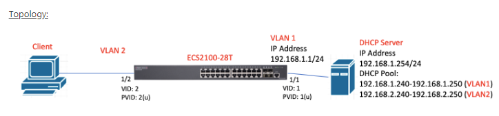
Configuration on ECS2100-28T:
1) Configure the port 2 to VLAN 2.
Console(config)#interface ethernet 1/2
Console(config-if)#switchport native vlan 2
Console(config-if)#switchport mode access
2) Set IP address on VLAN interface.
Console(config)#int vlan 1
Console(config-if)#ip address 192.168.1.1/24
Console(config-if)#exit
3) Enable the L2 DHCP relay and configure the IP address of DHCP server.
Console(config)#ip dhcp l2 relay
Console(config)#ip dhcp relay information option
Console(config)#ip dhcp relay server 192.168.1.254
L2 DHCP Relay packet forwarding procedures:
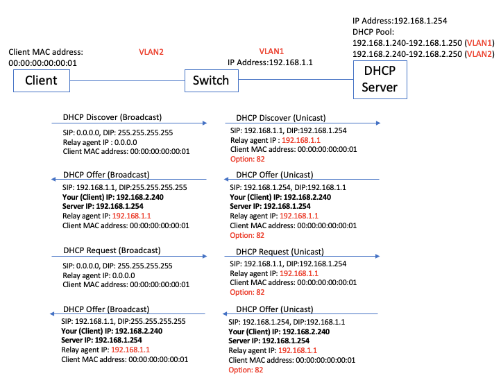
In this example, the client will get the IP address in the range of 192.168.2.240~192.168.250 from the DHCP server.
==================================================================
- L3 DHCP Relay
The L3 DHCP Relay function will convent the DHCP broadcast packet into the unicast packet and add the DHCP Relay agent IP address. Then DHCP server can refer to the Relay agent IP address to assigns the corresponding IP address.
Topology:
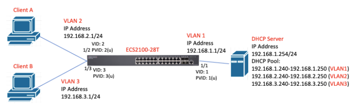
Configuration on ECS2100-28T:
1) Configure the port 2 to VLAN 2 and port 3 to VLAN 3.
Console(config)#interface ethernet 1/2
Console(config-if)#switchport native vlan 2
Console(config-if)#switchport mode access
Console(config-if)#exit
Console(config)#interface ethernet 1/3
Console(config-if)#switchport native vlan 3
Console(config-if)#switchport mode access
Console(config-if)#exit
2) Set IP address on VLAN interface.
Console(config)#int vlan 1
Console(config-if)#ip address 192.168.1.1/24
Console(config-if)#exit
Console(config)#int vlan 2
Console(config-if)#ip address 192.168.2.1/24
Console(config-if)#exit
Console(config)#int vlan 3
Console(config-if)#ip address 192.168.3.1/24
Console(config-if)#exit
3) Enable the L3 DHCP relay and configure DHCP relay server on VLAN interface.
Console(config)#ip dhcp l3 relay
Console(config)#int vlan 2
Console(config-if)#ip dhcp relay server 192.168.1.254
Console(config-if)#exit
Console(config)#int vlan 3
Console(config-if)#ip dhcp relay server 192.168.1.254
Console(config-if)#exit
L3 DHCP Relay packet forwarding procedures:
Example of client B.
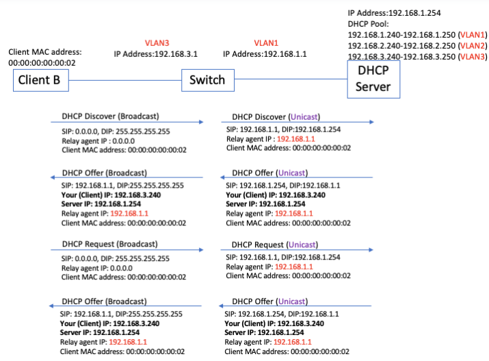
In this example,
Client A can get the IP address in the range of 192.168.2.240-250 the DHCP server.
Client B can get the IP address in the range of 192.168.3.240-250 the DHCP server.
How to upgrade ECS4120 loader version to extend the ECC (Error Correcting code) support?
The ECS4120 Loader version 0.0.3.1 support ECC (Error Correcting code).
Environment and Preparation:
- The ECS4120 switch MUST with the loader version 0.0.2.6 or 0.0.3.0. Check it by the command "show version". (If your version is not 0.0.2.6 or 0.0.3.0, please DO NOT run the script.)
- Windows PC(Win7, Win8 or Win10) with one Serial COM port
- Script - ECS4120_uboot_upgrade_v2.0.0.zip
Configuration: Modify config.ini
- [serial] section: Serial COM port
Caution: DO NOT modify [product] section's "type" parameter in the config.ini
Example:
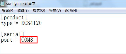
How to check Serial COM port on the PC?
In Device Manager (Start -> Run -> devmgmt.msc)
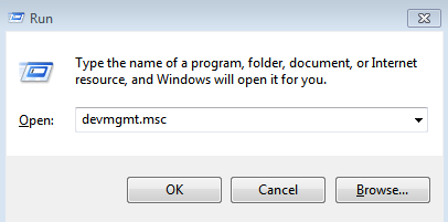
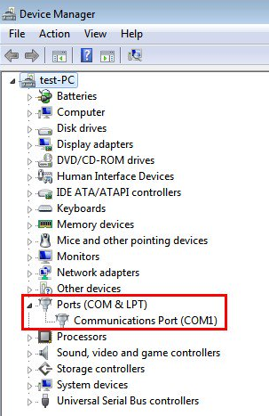
Caution:
Before running the script, please turn OFF all the terminals on the PC and power OFF the Switch.
Upgrade loader:
Step 1: Run the script “uboot_upgarde.exe”.
Double click “uboot_upgrade.exe” to run the script.
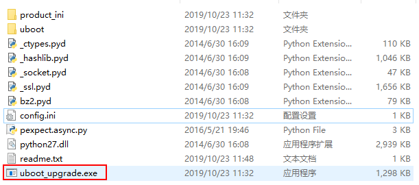
Step 2: Power ON the switch
The script will execute automatically.
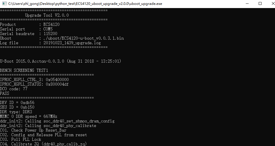
After upgrading, uboot_upgrade.exe will close by itself.
Caution:
When running the script, please DO NOT remove the console cable and unplug the power cord.
If it failed to upgrade, please send your request and log file to [email protected].
Supported models: ECS4120 series (V1.2.2.13)
SNMPSET command format.
snmpset -v 2c -c private {switch IP Address} {inetCidrRouteStatus}.{IPv4 or IPv6}.{Destination network segment}.{mask}.{IPv4 or IPv6}.{Next hop} {integer} {value}
{inetCidrRouteStatus}
- OID: 1.3.6.1.2.1.4.24.7.1.17
{IPv4 or IPv6}
- IPv4 OID: 1.4 --> 1 = IPv4 , 4 = IPv4 address is 4 byte.
- IPv6 OID: 2.16 --> 2 = IPv6 , 16 = IPv6 address is 16 byte. (Please indicate in decimal. e.g. 2002::1 = 32.2.0.0.0.0.0.0.0.0.0.0.0.0.0.1)
{value}
- 4 = Active
- 6 = Destroy
Configure IPv4 static route via SNMP.
- Adding a IPv4 static route as follow:
ip route 192.168.87.0 255.255.255.0 192.168.2.11
- NET-SNMP command:
snmpset -v 2c -c private 192.168.2.10 1.3.6.1.2.1.4.24.7.1.17.1.4.192.168.87.0.24.1.4.192.168.2.11 i 4
Configure IPv6 static route via SNMP.
- Adding a IPv6 static route as follow:
ipv6 route 2002:8787::/64 2002::1
- NET-SNMP command:
snmpset -v 2c -c private 192.168.2.10 1.3.6.1.2.1.4.24.7.1.17.2.16.32.2.135.135.0.0.0.0.0.0.0.0.0.0.0.0.64.2.16.32.2.0.0.0.0.0.0.0.0.0.0.0.0.0.1 i 4
Result:
!
interface vlan 1
ip address 192.168.2.10 255.255.255.0
!
interface craft
!
!
ip route 192.168.87.0 255.255.255.0 192.168.2.11
!
!
interface vlan 1
ipv6 address 2002::1/64
!
ipv6 route 2002:8787::/64 2002::1
!
The basic DHCPSNP topology and configuration on the switch as below.
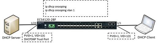
Original Behavior: (Not support “vlan-flooding” command or “vlan-flooding” enabled.)
When the switch enabled DHCPSNP function globally, the client will request the IP address by sending out the DHCP packets (Discover/Request) to untrust port.
This DHCP packet belongs to the vlan which includes in DHCPSNP enable vlan list, the switch will forward it to trust port only which is also the vlan member.
If this DHCP packet belongs to the vlan which doesn’t include in DHCPSNP enable vlan list, the switch will forward/flood it to ALL other ports which are also the vlan member.
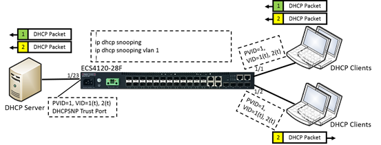
Disabled DHCPSNP vlan-flooding Behavior: (vlan-flooding is enabled on switch by default.)
The mechanism is the same when the DHCP packet belongs to the vlan which includes in DHCPSNP enable vlan list.
However, if this DHCP packet belongs to the vlan which doesn’t include in DHCPSNP enable vlan list, the switch will NOT forward/flood it to any other port which is also the vlan member.
The user could easily configure how the DHCP packets forward on switch ports.
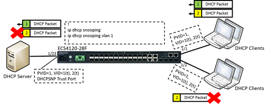
[Result]
When the DHCP packets - Discover/Request from the clients is received.
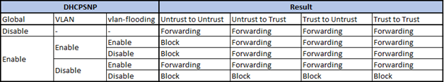
Configuration via CLI/WEB/SNMP.
CLI command
Default is vlan-flooding enabled.
Console#con
Console(config)#interface ethernet 1/1
Console(config-if)#ip dhcp snooping vlan-flooding ---> Enabled
or
Console(config-if)#no ip dhcp snooping vlan-flooding ---> Disabled

WEB
Security > DHCP Snooping > Step: 3. Configure Interface > Enabled/Disabled Vlan Flooding
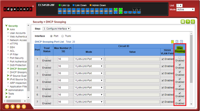
SNMP
[SNMPSET command format]
snmpset -v 2c -c private {switch ip} {dhcpSnoopPortVlanFlooding}.{dhcpSnoopPortIfIndex} {integer} {value}
For dhcpSnoopPortVlanFlooding, OID 1.3.6.1.4.1.259.10.1.45.1.46.3.1.1.7
Set OID 1.3.6.1.4.1.259.10.1.45.1.46.3.1.1.7 to enabled(1) vlan flooding.
Set OID 1.3.6.1.4.1.259.10.1.45.1.46.3.1.1.7 to disabled(2) vlan flooding.
For dhcpSnoopPortIfIndex: The port interface of dhcpSnoopPortIfIndex
The ifIndex value of the port or trunk.
Enabled vlan flooding.

Disabled vlan flooding.

Support models and software version:
ECS4120 series v1.2.2.23 and above
- Enable IPv6 source guard or IPv6 prefix guard on port interface configuration and set maximum binding number.
ipv6 source-guard { sip | sdp | max-binding }
Console#con
Console(config)#interface ethernet 1/1
Console(config-if)#ipv6 source-guard sdp
Console(config-if)#ipv6 source-guard max-binding 3
Console(config-if)#end
Console#show ipv6 source-guard
Interface   Filter-type   Max-binding
---------   -----------   -----------
Eth 1/1     SDP                     3
Eth 1/2     DISABLED                5
Eth 1/3     DISABLED                5
- Add static IPv6 source guard or IPv6 prefix guard binding entry on global configuration mode.
ipv6 source-guard binding Mac-Address vlan VLAN_ID { IPv6-Address | IPv6-Prefix } interface ethernet Unit/Port
Console#con
Console(config)#ipv6 source-guard binding 90-E6-BA-63-96-CD vlan 1 2001:b000:2::/64 interface ethernet 1/21
Console(config)#end
Console#show ipv6 source-guard binding
DHCPV6SNP:
 DHCP - Stateful address
NDSNP:
 ND - Stateless address
STA - Static IPv6 source guard binding

MAC Address    IPv6 Address/IPv6 Prefix                VLAN Interface Type
-------------- --------------------------------------- ---- --------- ----
90E6-BA63-96CD                        2001:b000:2::/64    1  Eth 1/21  STA
- Enable IPv6 source guard or IPv6 prefix guard on port interface configuration and set maximum binding number.
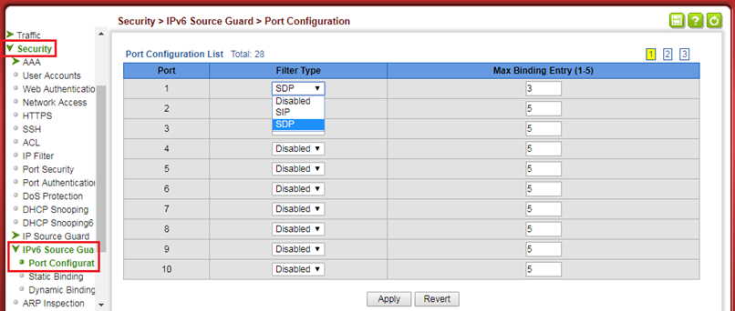
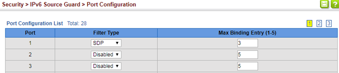
- Add static ipv6 source guard or ipv6 prefix guard binding entry on the switch.
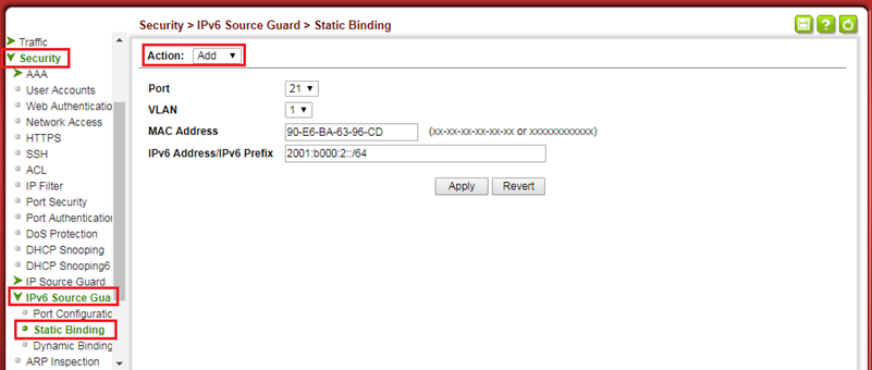
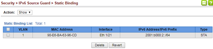
- Enable IPv6 source guard or IPv6 prefix guard on port interface configuration and set maximum binding number.
C:\>snmpwalk -v 2c -c private 192.168.1.1 1.3.6.1.4.1.259.10.1.45.1.74.1.1.2.24
SNMPv2-SMI::enterprises.259.10.1.45.1.74.1.1.2.24 = INTEGER: 1
C:\>snmpset -v 2c -c private 192.168.1.1 1.3.6.1.4.1.259.10.1.45.1.74.1.1.2.24 i 3
SNMPv2-SMI::enterprises.259.10.1.45.1.74.1.1.2.24 = INTEGER: 3
C:\>snmpwalk -v 2c -c private 192.168.1.1 1.3.6.1.4.1.259.10.1.45.1.74.1.1.2.24
SNMPv2-SMI::enterprises.259.10.1.45.1.74.1.1.2.24 = INTEGER: 3
C:\>snmpset -v 2c -c private 192.168.1.1 1.3.6.1.4.1.259.10.1.45.1.74.1.1.3.24 i 3
SNMPv2-SMI::enterprises.259.10.1.45.1.74.1.1.3.24 = INTEGER: 3
Console#show ipv6 source-guard
Interface   Filter-type   Max-binding
---------   -----------   -----------
Eth 1/23    DISABLED                5
Eth 1/24    SDP                     3
Eth 1/25    DISABLED                5
- Add a static IPv6 source guard or IPv6 prefix guard binding entry on the switch.
Console#show ipv6 source-guard binding
DHCPV6SNP:
 DHCP - Stateful address
NDSNP:
 ND - Stateless address
STA - Static IPv6 source guard binding

MAC Address    IPv6 Address/IPv6 Prefix                VLAN Interface Type
-------------- --------------------------------------- ---- --------- ----
382C-4A77-DD37                      2001:db8:2222::/64    1  Eth 1/24 DHCP
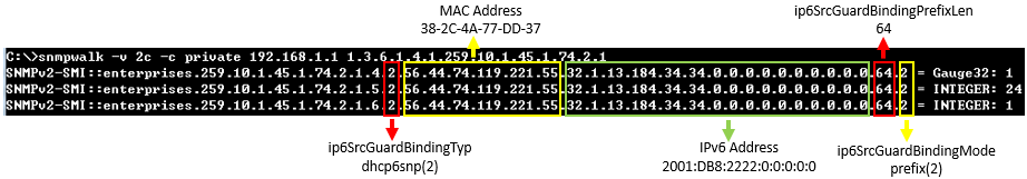
C:\>snmpwalk -v 2c -c private 192.168.1.1 1.3.6.1.4.1.259.10.1.45.1.74.2.1
SNMPv2-SMI::enterprises.259.10.1.45.1.74.2.1.4.2.56.44.74.119.221.55.32.1.13.184.34.34.0.0.0.0.0.0.0.0.0.0.64.2 = Gauge32: 1  -> VLAN=1
SNMPv2-SMI::enterprises.259.10.1.45.1.74.2.1.5.2.56.44.74.119.221.55.32.1.13.184.34.34.0.0.0.0.0.0.0.0.0.0.64.2 = INTEGER: 24  -> Port=Eth1/24
SNMPv2-SMI::enterprises.259.10.1.45.1.74.2.1.6.2.56.44.74.119.221.55.32.1.13.184.34.34.0.0.0.0.0.0.0.0.0.0.64.2 = INTEGER: 1  -> Status=Active(1)
C:\>snmpset -v 2c -c private 192.168.1.1 1.3.6.1.4.1.259.10.1.45.1.74.2.1.6.1.144.230.186.99.150.205.32.1.176.0.0.2.0.0.0.0.0.0.0.0.0.0.64.2 i 5
SNMPv2-SMI::enterprises.259.10.1.45.1.74.2.1.6.1.144.230.186.99.150.205.32.1.176.0.0.2.0.0.0.0.0.0.0.0.0.0.64.2 = INTEGER: 5
C:\>snmpset -v 2c -c private 192.168.1.1 1.3.6.1.4.1.259.10.1.45.1.74.2.1.4.1.144.230.186.99.150.205.32.1.176.0.0.2.0.0.0.0.0.0.0.0.0.0.64.2 u 1
SNMPv2-SMI::enterprises.259.10.1.45.1.74.2.1.4.1.144.230.186.99.150.205.32.1.176.0.0.2.0.0.0.0.0.0.0.0.0.0.64.2 = Gauge32: 1
C:\>snmpset -v 2c -c private 192.168.1.1 1.3.6.1.4.1.259.10.1.45.1.74.2.1.5.1.144.230.186.99.150.205.32.1.176.0.0.2.0.0.0.0.0.0.0.0.0.0.64.2 i 21
SNMPv2-SMI::enterprises.259.10.1.45.1.74.2.1.5.1.144.230.186.99.150.205.32.1.176.0.0.2.0.0.0.0.0.0.0.0.0.0.64.2 = INTEGER: 21
C:\>snmpset -v 2c -c private 192.168.1.1 1.3.6.1.4.1.259.10.1.45.1.74.2.1.6.1.144.230.186.99.150.205.32.1.176.0.0.2.0.0.0.0.0.0.0.0.0.0.64.2 i 1
SNMPv2-SMI::enterprises.259.10.1.45.1.74.2.1.6.1.144.230.186.99.150.205.32.1.176.0.0.2.0.0.0.0.0.0.0.0.0.0.64.2 = INTEGER: 1
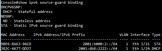
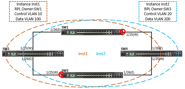
SW1#configure
SW1(config)#interface ethernet 1/1
SW1(config-if)#switchport allowed vlan add 100,200,300 tagged
SW1(config-if)#exit
SW1(config)#interface ethernet 1/25
SW1(config-if)#switchport allowed vlan add 10,20,100,200,300 tagged
SW1(config-if)#spanning-tree spanning-disabled
SW1(config-if)#exit
SW1(config)#interface ethernet 1/26
SW1(config-if)#switchport allowed vlan add 10,20,100,200,300 tagged
SW1(config-if)#spanning-tree spanning-disabled
SW1(config-if)#exit
SW1(config)#erps
SW1(config)#erps vlan-group group1 add 10,100
SW1(config)#erps vlan-group group2 add 20,200
SW1(config)#erps ring Ring
SW1(config-erps-ring)#ring-port west interface ethernet 1/25
SW1(config-erps-ring)#ring-port east interface ethernet 1/26
SW1(config-erps-ring)#enable
SW1(config-erps-ring)#exit
SW1(config)#erps instance inst1 id 1
SW1(config-erps-inst)#control-vlan 10
SW1(config-erps-inst)#rpl owner
SW1(config-erps-inst)#physical-ring Ring
SW1(config-erps-inst)#inclusion-vlan group1
SW1(config-erps-inst)#enable
SW1(config-erps-inst)#exit
SW1(config)#erps instance inst2 id 2
SW1(config-erps-inst)#control-vlan 20
SW1(config-erps-inst)#physical-ring Ring
SW1(config-erps-inst)#inclusion-vlan group2
SW1(config-erps-inst)#enable
SW1(config-erps-inst)#end
SW2#configure
SW2(config)#interface ethernet 1/1
SW2(config-if)#switchport allowed vlan add 100,200,300 tagged
SW2(config-if)#exit
SW2(config)#interface ethernet 1/25
SW2(config-if)#switchport allowed vlan add 10,20,100,200,300 tagged
SW2(config-if)#spanning-tree spanning-disabled
SW2(config-if)#exit
SW2(config)#interface ethernet 1/26
SW2(config-if)#switchport allowed vlan add 10,20,100,200,300 tagged
SW2(config-if)#spanning-tree spanning-disabled
SW2(config-if)#exit
SW2(config)#erps
SW2(config)#erps vlan-group group1 add 10,100
SW2(config)#erps vlan-group group2 add 20,200
SW2(config)#erps ring Ring
SW2(config-erps-ring)#ring-port west interface ethernet 1/25
SW2(config-erps-ring)#ring-port east interface ethernet 1/26
SW2(config-erps-ring)#enable
SW2(config-erps-ring)#exit
SW2(config)#erps instance inst1 id 1
SW2(config-erps-inst)#control-vlan 10
SW2(config-erps-inst)#physical-ring Ring
SW2(config-erps-inst)#inclusion-vlan group1
SW2(config-erps-inst)#enable
SW2(config-erps-inst)#exit
SW2(config)#erps instance inst2 id 2
SW2(config-erps-inst)#control-vlan 20
SW2(config-erps-inst)#physical-ring Ring
SW2(config-erps-inst)#inclusion-vlan group2
SW2(config-erps-inst)#enable
SW2(config-erps-inst)#end
SW3#configure
SW3(config)#interface ethernet 1/1
SW3(config-if)#switchport allowed vlan add 100,200,300 tagged
SW3(config-if)#exit
SW3(config)#interface ethernet 1/25
SW3(config-if)#switchport allowed vlan add 10,20,100,200,300 tagged
SW3(config-if)#spanning-tree spanning-disabled
SW3(config-if)#exit
SW3(config)#interface ethernet 1/26
SW3(config-if)#switchport allowed vlan add 10,20,100,200,300 tagged
SW3(config-if)#spanning-tree spanning-disabled
SW3(config-if)#exit
SW3(config)#erps
SW3(config)#erps vlan-group group1 add 10,100
SW3(config)#erps vlan-group group2 add 20,200
SW3(config)#erps ring Ring
SW3(config-erps-ring)#ring-port west interface ethernet 1/25
SW3(config-erps-ring)#ring-port east interface ethernet 1/26
SW3(config-erps-ring)#enable
SW3(config-erps-ring)#exit
SW3(config)#erps instance inst1 id 1
SW3(config-erps-inst)#control-vlan 10
SW3(config-erps-inst)#physical-ring Ring
SW3(config-erps-inst)#inclusion-vlan group1
SW3(config-erps-inst)#enable
SW3(config-erps-inst)#exit
SW3(config)#erps instance inst2 id 2
SW3(config-erps-inst)#control-vlan 20
SW3(config-erps-inst)#rpl owner
SW3(config-erps-inst)#physical-ring Ring
SW3(config-erps-inst)#inclusion-vlan group2
SW3(config-erps-inst)#enable
SW3(config-erps-inst)#end
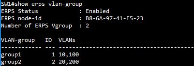
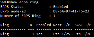
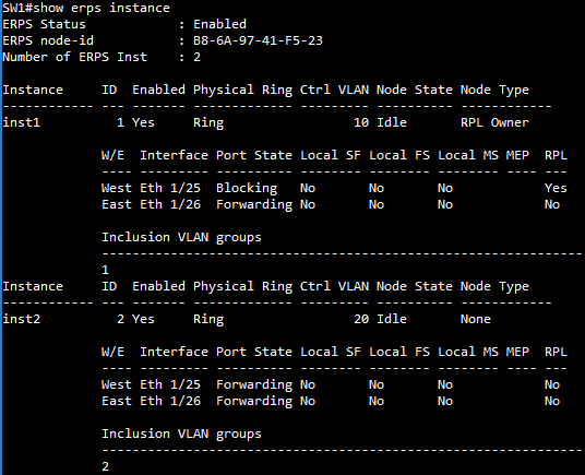
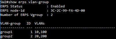
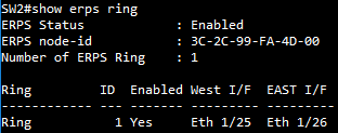

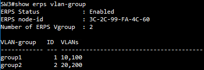
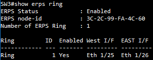
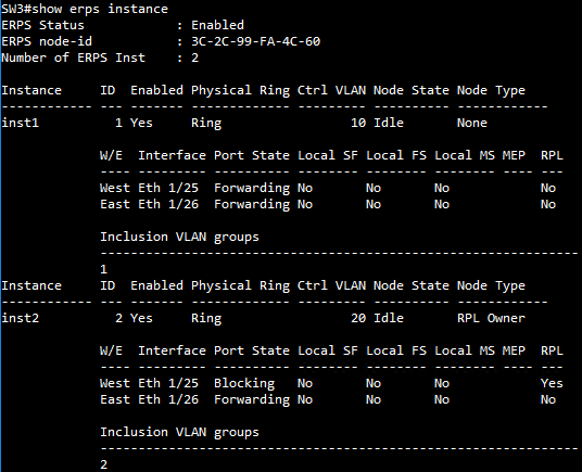
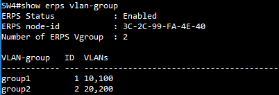
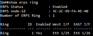
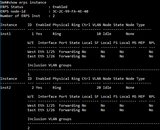
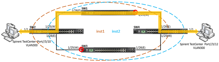
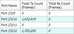
To prevent VLAN300 on ports of the logical line from being blocked by ERPS, the user can configure physical rings to form the line topology.
SW1(config)#erps vlan-group group3 add 300
SW1(config)#erps ring Ring
SW1(config-erps-ring)#no enable
SW1(config-erps-ring)#exclusion-vlan group3
SW1(config-erps-ring)#enable
SW2(config)#erps vlan-group group3 add 300
SW2(config)#erps ring Ring
SW2(config-erps-ring)#no enable
SW2(config-erps-ring)#exclusion-vlan group3
SW2(config-erps-ring)#enable
SW4(config)#erps vlan-group group3 add 300
SW4(config)#erps ring Ring
SW4(config-erps-ring)#no enable
SW4(config-erps-ring)#exclusion-vlan group3
SW4(config-erps-ring)#enable
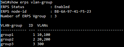
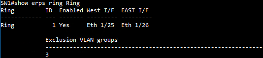
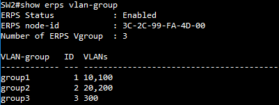
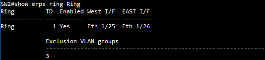
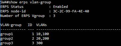
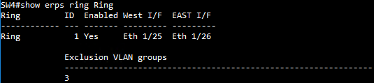
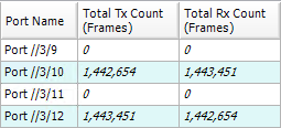
The management agent of Edgecore switches support SNMP (Simple Network Management Protocol).
This SNMP agent permits the switch to be managed from any system in the network using network management software.
Zabbix:
Zabbix is an open-source tool for monitoring the status of the server and device (switch, router...etc).
Available platforms:
OS: Ubuntu, CentOS, MAC
Necessary tool: Docker
Install the Zabbix procedure:
Step 1: Make sure the Docker is installed on this device.
Step 2: Get the repository on the GitHub. (https://github.com/zabbix/zabbix-docker.git)
git clone https://github.com/zabbix/zabbix-docker.git
Step 3: Enter the folder of the zabbix-docker
cd zabbix-docker
Step 4: Install and start up the Zabbix service.
docker-compose -f docker-compose_v3_alpine_mysql_latest.yaml up -d
Step 5: Open the web browser. (http://Your Server IP Address)
Username: Admin
Password: zabbix
Create the template for Edgecore switch:
This example is monitoring the temperature of the ECS4120-28T.
Procedure:
Step 1: Create the template
Configuration -> Templates -> Create template
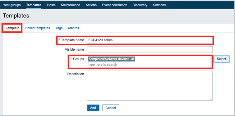
Step 2: Create the host
Configuration -> Hosts -> Create host
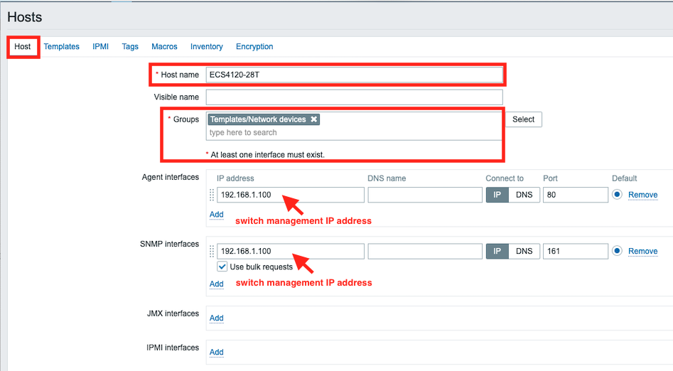
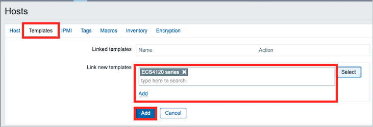
Step 3: Create an application on the host.
ECS4120-28T -> Application -> Create application
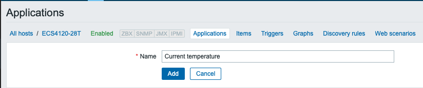
Step 4: Create an item on the host.
ECS4120-28T -> Item -> Create item
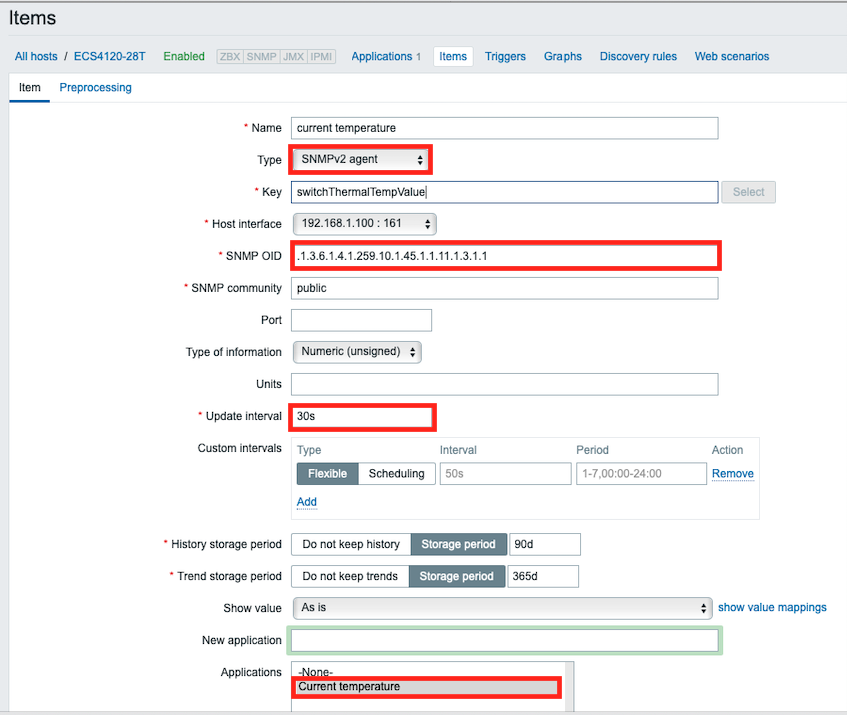
Step 5: On the home page, create a graph of temperature on the Dashboard.
Zabbix -> edit dashboard -> Add widget
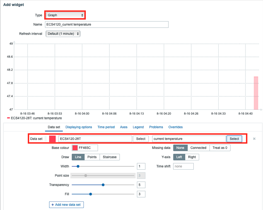
Step 6: Now, you can monitor the temperature of the ECS4120 Series via the Zabbix.
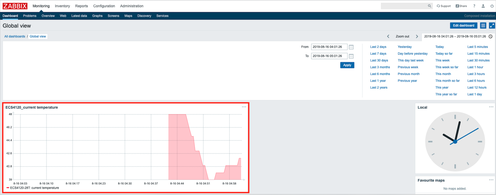
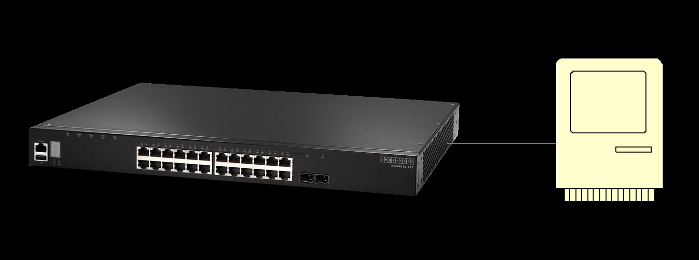
Product Model & Software
ECS4510-28T firmware version: v1.5.2.16
SNMP Server software: MG-soft v10.0.0.4044
Configure Procedures
1. Setting an IP address on ECS4510-28T.
Console(config)#interface vlan 1
Console(config-if)#ip address 192.168.1.1 255.255.255.0
2. Specifies an “engine-id” for the SNMP server.
Console(config)#snmp-server engine-id remote 192.168.1.20 8000052301c0a80114
*Please find the engine-id from your SNMP server.
The “engine-id” is automatically generated that is unique to the host.
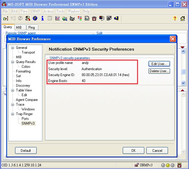
3. Create a remote SNMPv3 user.
Console(config)#snmp-server user andy super remote 192.168.1.20 v3 auth md5 andytest
* Also need to create a same user on your SNMP server.
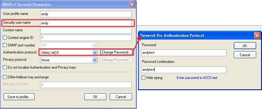
4. Create an SNMP “view entry” which controls user access to the MIB for the specific notification message.
Console(config)#snmp-server view super 1.3.6.1.4.1.259.10.1.24.* included.
*This example OID could access to whole the MIB tree of ECS4510-28T.
5. Create an SNMP group sets the access policy for the assigned users, and mapping SNMP users to SNMP views.
Console(config)#snmp-server group super v3 auth
6. Specify the target SNMP server that will receive inform messages.
Console(config)#snmp-server host 192.168.1.20 inform andy version 3 auth
*If we specify an SNMP Version 3 host, then the community-string is interpreted as an SNMP user name.
Thus here community-string “andy” is the user name.
7. SNMP informs collector will receive the SNMPv3 trap.
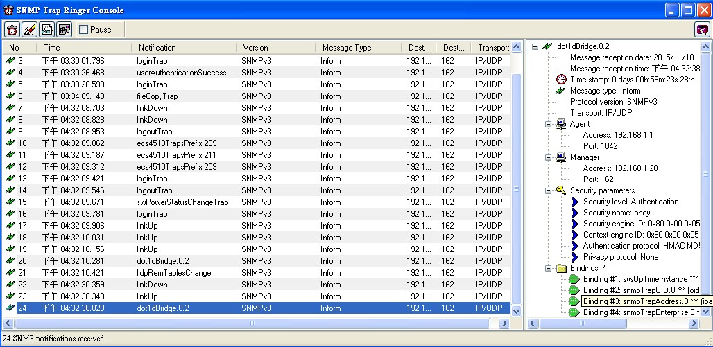
Troubleshooting
If the SNMP server still can’t receive the trap message from switch.
Please continue to capture SNMP packet on the SNMP server, then you could start to do the troubleshooting.
Generally it can be divided into the following two cases.
1) Host has not received the SNMP packets. >>> check the configuration of the switch.
-----------------------------------Switch’s Configuration Example-----------------------------------------------------
!
snmp-server engine-id remote 192.168.1.20 8000052301c0a80114
snmp-server group super v3 auth
snmp-server user andy super remote 192.168.1.20 v3 auth md5 andytest
snmp-server view super 1.3.6.1.4.1.259.10.1.24.* included
snmp-server host 192.168.1.20 inform andy version 3 auth
!
!
interface vlan 1
ip address 192.168.1.1/24
!
-----------------------------------Switch’s Configuration End------------------------------------------------------------
2) Host has received the SNMP packets. >>> check the engine-ID and user profile of SNMP server and switch.
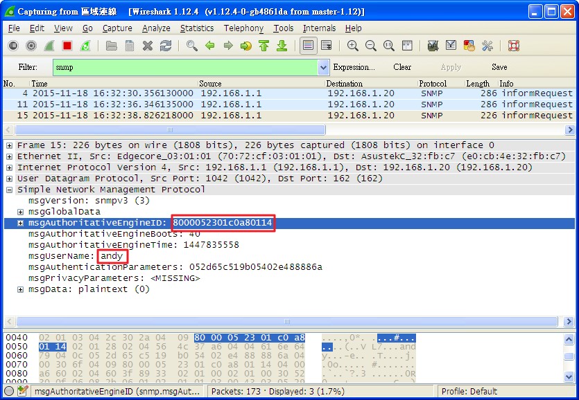
Problem description:
When user would like to enable IPv6 RA Guard on port interface by command below, but it display failed.
Console#con
Console(config)#interface ethernet 1/1
Console(config-if)#ipv6 nd raguard
Failed to configure IPv6 RA Guard on port 1/1.
Console(config-if)#
Solution:
To sloved rules number issue on ECS4210 series, R&D add new feature for dynamic TCAM allocation.
About IPv6 RA Guard, it's IPv6 rule.
According to tcam design, you must change to 'default' mode then could enable IPv6 RA Guard.(default is ipv4 mode)
Console(config)#tcam allocation ?
default allocate one slice for MAC, one slice for IPv4, two slices for IPv6
ipv4 allocate one slice for MAC, three slices for IPv4, no slices for IPv6
mac allocate two slices for MAC, one slice for IPv4, no slices for IPv6
Console(config)#tcam allocation default
please remember save the config and reboot the switch, then new allocation will apply.
When you use IPv4/MAC mode, it will share IPv6 table to IPv4/MAC.
On 'IPv4' or 'MAC' mode, it will always fail to enable IPv6 RA Guard.
[Reason]
Chip have symptom for the limit number of ACLs.
[Target]
Dynamic to allocate superfluous rules to other rules.
[Action] .
==default mode==
MAC rules: 128 rules share with MAC ACL, MAC service policy and reserved rules.
IPv4 rules: 128 rules share with IPv4 ACL, IPv4 service policy and reserved rules.
IPv6 rules: 128 rules share with IPv6 ACL, IPv6 service policy and reserved rules.
==IPv4 mode==
MAC rules: 128 rules share with MAC ACL, MAC service policy and reserved rules.
IPv4 rules: 128 rules share with IPv4 ACL. 256 rules share with IPv4 service policy.
IPv6 rules: 0 rules.
==mac mode==
MAC rules: 128 rules share with MAC ACL and reserved rules. 128 rules share with MAC service policy.
IPv4 rules: 128 rules share with IPv4 ACL, IPv4 service policy and reserved rules.
IPv6 rules: 0 rules.
Topology

A. Configuration


B. Check ERPS status
ERPS status on S1 (RPL Owner)

ERPS status on S3

ERPS status on S5

C. Disconnect the link between Agg2 and S5.

With ERPS recovery procedure, the RPL owner node detects a failed link when it receives R-APS (SF - signal fault) messages from nodes adjacent to the failed link. The RPL owner then enters protection state by unblocking the West port. However, using this standard recovery procedure may cause a non-EPRS device to become isolated when the ERPS device adjacent to it detects a continuity check message (CCM) loss event and blocks the link between the non-ERPS device and ERPS device.
ERPS domain status on S1

ERPS domain status on S5

D. Enable non-ERPS device protection
If non-ERPS device protection is enabled on the ring, the ring ports on the RPL owner node and non-owner nodes will not be blocked when signal loss is detected by CCM loss events. When non-ERPS device protection is enabled on a RPL owner node, it will send non-standard health-check packets to poll the ring health when it enters the protection state.
Enable non-ERPS device protection on S1 and S5.


When ERPS status was changed to protection mode, port 24 on S1 become forwarding, and non-ERPS device will not be isolated.
ERPS and domain status on S1


1. Enable the PPPoE Intermediate Agent globally on the switch.
Console(config)#pppoe intermediate-agent
2. Enable PPPoE Intermediate Agent and set to trusted mode at the interface that is connected to a PPPoE server.
Console(config)#interface ethernet 1/24
Console(config-if)#pppoe intermediate-agent port-enable
Console(config-if)#pppoe intermediate-agent trust
3. Enables PPPoE Intermediate Agent at the interface that is connected to a PPPoE client.
Console(config)#interface ethernet 1/1
Console(config-if)#pppoe intermediate-agent port-enable
4. Check the Intermediate Agent information on the ports.

5. We can capture the packets on the PPPoE server to know whether the PPPoE connection it is success or not. Besides, we can specify circuit ID string to tagged to PPPoE packets that send to server from clients.
Default circuit ID string at PPPoE Tags:

Specified circuit ID string at PPPoE Tags with following command:
Console(config)# pppoe intermediate-agent format-type access-node-identifier ECS4110
Console(config)#interface ethernet 1/1
Console(config-if)# pppoe intermediate-agent port-format-type circuit-id TEST

6. We also can check the statistics information of the PPPoE Intermediate Agent on the switch.

Topology:

Before we apply the ACL to switch, we can access to WEB/FTP service and ping.

1) Set ACL depend on IP address.
Configuration:
*Create ACL "aclip" and set rule. (Deny client access to the specific IP.)
Console(config)# access-list ip extended aclip
Console(config-ext-acl)# deny ip host 192.168.20.10 host 192.168.20.150
Console(config-ext-acl)# exit
*Apply the ACL to specific port on switch.
Console(config)# interface ethernet 1/2
Console(config-if)# ip access-group aclip in

Results:
Client (192.168.20.10) cannot ping and access to WEB and FTP (192.168.20.150), but available Ping to others IP address.


2) Set ACL depend on IP and TCP.
Configuration:
*Create ACL "acltcp" and set rule. (Deny client using TCP access to the specific IP.)
Console(config)#access-list ip extended acltcp
Console(config-ext-acl)#deny tcp host 192.168.20.10 host 192.168.20.150
Console(config-ext-acl)#exit
*Apply ACL to specific port on switch.
Console(config)#int ethernet 1/2
Console(config-if)#ip access-group acltcp in

Results:
Client (192.168.20.10) cannot access to WEB and FTP, but available Ping and access to TFTP (192.168.20.150).


3) Set ACL depend on IP and UDP.
Configuration:
*Create ACL "acludp" and set rule. (Deny client using UDP access to specific IP)
Console(config)#access-list ip extended acludp
Console(config-ext-acl)#deny udp host 192.168.20.10 host 192.168.20.150
Console(config-ext-acl)#exit
*Apply ACL to specific port on switch.
Console(config)#int ethernet 1/2
Console(config-if)#ip access-group acludp in

Results:
Client (192.168.20.10) cannot access to TFTP, but available Ping and access to the WEB/FTP (192.168.20.150).


4) Set the ACL depend on IP and port number.
Configuration:
*Create ACL "aclport" and set rule. (Deny client access specific IP address and port number.)
Console(config)#access-list ip extended aclport
Console(config-ext-acl)#deny host 192.168.20.10 host 192.168.20.150 destination-port 21
Console(config-ext-acl)#exit
*Apply the ACL to specific port on switch.
Console(config)#int ethernet 1/2
Console(config-if)#ip access-group aclport in

Results:
Client (192.168.20.10) cannot access FTP, but available Ping and access to WEB/TFTP (192.168.20.150).


Model
ECS4110-28P
- Configure the freeRADIUS server
vi /etc/freeradius/client.conf
client 192.168.1.0/24 {
secret = testing123
shortname = private-network-1
}
vi /etc/freeradius/eap.conf
default_eap_type = md5
vi /etc/freeradius/users
test User-Password := 'test'
NOTE:
The RADIUS server may optionally return dynamic QoS assignments to be applied to a switch port for an authenticated user. The "Filter-ID" attribute (attribute 11) can be configured on the RADIUS server to pass the following QoS information:

p.s. Refer the management guide manual.
- Set IP address on VLAN 1
Console(config)#interface vlan 1
Console(config-if)#ip address 192.168.1.1 255.255.255.0
Console(config-if)#exit
- Specifies the RADIUS servers and the corresponding secret key
- Enables dot1x globally on the switch
- Enables dot1x mode and dynamic QoS feature on port 1
Console(config-if)#dot1x port-control auto
Console(config-if)#network-access dynamic-qos
Console(config-if)#exit
Console(config)#
- Enables authentication methods with the MD5-Challenge on the TESTPC1's network card.

p.s. How to re-enable EAP-MD5 support in versions of Windows Vista or Windows 7?
http://support.microsoft.com/kb/922574/en-us
- Connect the PC to the switch port 1 then click the pop-up message.

- Enter the username and password.

- Check the result.

Topology
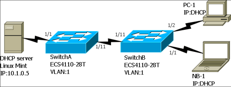
At this example, we will configure 3 DHCP IP pools on the DHCP server. (DHCP server of Linux-mint)
1. Range 10.1.1.100 ~ 10.1.1.200, mask 255.255.255.0
2. Range 10.1.2.100 ~ 10.1.2.200, mask 255.255.255.0
3. Range 10.1.3.100 ~ 10.1.3.200, mask 255.255.255.0
Before set those rules on the DHCP server, you should know what you want to filter. At this example we will use Circuit ID as filter conditions.
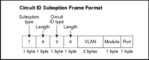
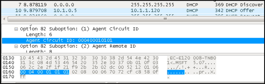
Linux-mint DHCP server configuration:
vi /etc/dhcp/dhcpd.cfg
default-lease-time 600;
max-lease-time 7200;
option domain-name-servers 8.8.8.8; #DNS server
# Here will use last two bits of circuit-id as filter condition.
class 'keep1'{
match if(substring(option agent.circuit-id,4,2)=01:01)
}When PC-1 insert SwitchB E 1/1.
class 'keep2'{
match if(substring(option agent.circuit-id,4,2)=01:02)
} # When NB-1 insert SwitchB E 1/2.
class 'replace'{
match if(substring(option agent.circuit-id,4,2)=01:0B);
} # Replace will be change to SwitchA circuit-id.
#Set the pools on DHCP server.
shared-network group{
subnet 10.1.0.0 netmask 255.255.0.0{
pool {
allow members of 'keep1';
range 10.1.1.100 10.1.1.200;
option subnet-mask 255.255.255.0;
}
pool {
allow members of 'keep2'
range 10.1.2.100 10.1.2.200;
option subnet-mask 255.255.255.0;
}
pool {
allow members of 'replace';
range 10.1.0.100 10.1.0.200;
option subnet-mask 255.255.255.0;
}}}
Now we already finish the settings on the DHCP server.
Here we want configure DHCP option 82 at the switches:
Example 1:
If we want to let PC-1 and NB-1 get ip from the DHCP pools “keep1” and “keep2”, we should let SwitchA keep the SwitchB DHCP option 82.
SwitchA setting
Step-1: Enable ip dhcp snooping with DHCP option 82
switchA(config)#ip dhcp snooping information option
Step-2: Set the policy as “keep”
switchA(config)#ip dhcp snooping information policy keep
SwitchB setting
Step-1: Enable ip dhcp snooping globally
switchA#config
switchA(config)#ip dhcp snooping
Step-2: Enable ip dhcp snooping on vlan 1
switchA(config)#ip dhcp snooping vlan 1
Step-3: Enable ip dhcp snooping with DHCP option 82
switchA(config)#ip dhcp snooping information option
Step-4: Set trust port on port 11
switchA(config)#interface ethernet 1/11
switchA(config-if)#ip dhcp snooping trust
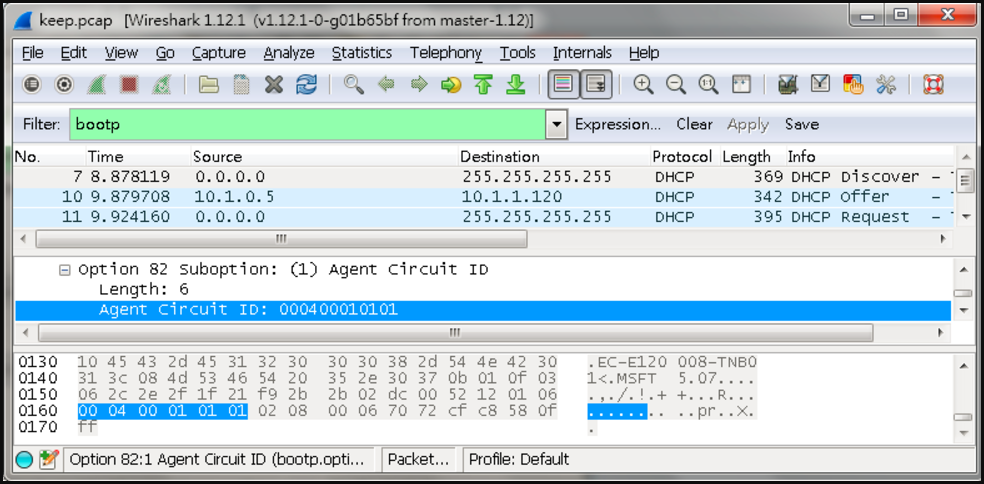
NB-1: DHCP Discover take the option 82 “Circuit ID: 000400010101”.
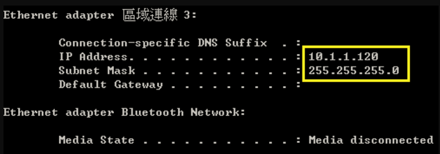
NB-1: So it can get IP “10.1.1.120” from DHCP pool “keep1”
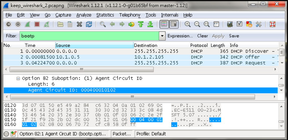
PC-1: So it can get IP “10.1.2.105” from DHCP pool “keep2”
Example 2:
If we want to let PC-1 and NB-1 get ip from the DHCP pools “replace”, we should let SwitchA replace the SwitchB DHCP option 82.
SwitchA setting
Step-1: Enable ip dhcp snooping with DHCP option 82
switchA(config)#ip dhcp snooping information option
Step-2: Set the policy as “replace”
switchA(config)#ip dhcp snooping information policy replace
SwitchB setting
Step-1: Enable ip dhcp snooping globally
switchA#config
switchA(config)#ip dhcp snooping
Step-2: Enable ip dhcp snooping on vlan 1
switchA(config)#ip dhcp snooping vlan 1
Step-3: Enable ip dhcp snooping with DHCP option 82
switchA(config)#ip dhcp snooping information option
Step-4: Set trust port on port 11
switchA(config)#interface ethernet 1/11
switchA(config-if)#ip dhcp snooping trust
Result
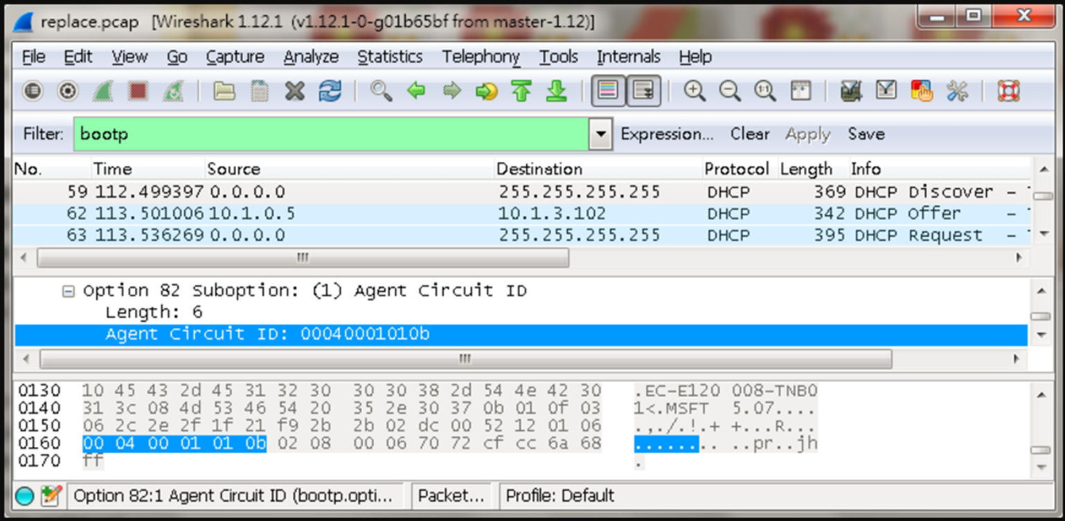
NB-1: DHCP Discover take the option 82 “Circuit ID: 00040001010b”.
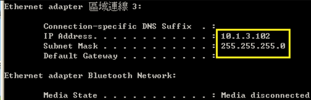
NB-1: So it can get IP “10.1.3.102” from DHCP pool “replace”
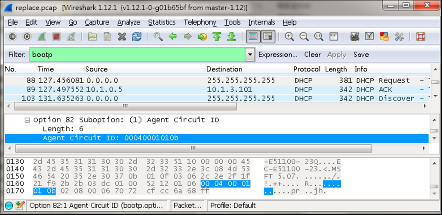
PC-1: DHCP Discover take the option 82 “Circuit ID: 00040001010b”.
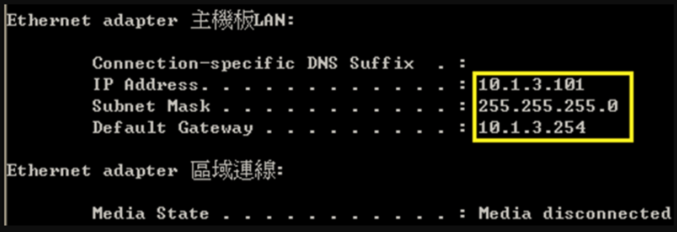
PC-1: So it can get IP “10.1.3.101” from DHCP pool “replace”
Notes:
If you only have one switch that don't need to set “ip dhcp snooping information policy”.
Config IPSG ACL mode, SIP-MAC, and set max-binding on port1.
(1) ipSrcGuardMode(Integer 2 : srcIpMac)
C:\>snmpset -v 2c -c private 192.168.1.90 1.3.6.1.4.1.259.10.1.27.1.48.1.1.2.1 i 2
SNMPv2-SMI::enterprises.259.10.1.27.1.48.1.1.2.1 = INTEGER: 2
(2) ipSrcGuardTableMode(Integer 1 : acl)
C:\>snmpset -v 2c -c private 192.168.1.90 1.3.6.1.4.1.259.10.1.27.1.48.1.1.3.1 i 1
SNMPv2-SMI::enterprises.259.10.1.27.1.48.1.1.3.1 = INTEGER: 1
(3) ipSrcGuardAclMaxBinding(Integer 3 : set mac count as 3)
C:\>snmpset -v 2c -c private 192.168.1.90 1.3.6.1.4.1.259.10.1.27.1.48.1.1.4.1 i 3
SNMPv2-SMI::enterprises.259.10.1.27.1.48.1.1.4.1 = INTEGER: 3
Console#show running-config interface ethernet 1/1
interface ethernet 1/1
ip source-guard sip-mac
ip source-guard mode acl max-binding 3
!
Config IPSG MAC mode, SIP, and set max-binding on port2.
(1) ipSrcGuardMode(Integer 1 : srcIp)
C:\>snmpset -v 2c -c private 192.168.1.90 1.3.6.1.4.1.259.10.1.27.1.48.1.1.2.2 i 1
SNMPv2-SMI::enterprises.259.10.1.27.1.48.1.1.2.2 = INTEGER: 1
(2) ipSrcGuardTableMode(Integer 2 : mac)
C:\>snmpset -v 2c -c private 192.168.1.90 1.3.6.1.4.1.259.10.1.27.1.48.1.1.3.2 i 2
SNMPv2-SMI::enterprises.259.10.1.27.1.48.1.1.3.2 = INTEGER: 2
(3) ipSrcGuardAclMaxBinding(Integer 5 : set mac count as 5)
C:\>snmpset -v 2c -c private 192.168.1.90 1.3.6.1.4.1.259.10.1.27.1.48.1.1.5.2 i 5
<Results>
SNMPv2-SMI::enterprises.259.10.1.27.1.48.1.1.5.2 = INTEGER: 5
Console#show running-config interface ethernet 1/2
interface ethernet 1/2
ip source-guard sip
ip source-guard mode mac
ip source-guard mode mac max-binding 5
!
Static bind an entry on port.
SNMPSET command format :
snmpset -v 2c -c private < ipSrcGuardAclBindingStatus | ipSrcGuardAclBindingVlanIndex | ipSrcGuardAclBindingPortIfIndex >. . .1(1 : static)
(1) ipSrcGuardAclBindingStatus(Integer 5 : create and wait)
C:\>snmpset -v 2c -c private 192.168.1.90 1.3.6.1.4.1.259.10.1.27.1.48.3.1.6.192.168.1.1.0.31.198.222.224.107.1 i 5
SNMPv2-SMI::enterprises.259.10.1.27.1.48.3.1.6.192.168.1.1.0.31.198.222.224.107.1 = INTEGER: 5
(2) ipSrcGuardAclBindingVlanIndex(Gauge 1001 : 1000+vlanID)
C:\>snmpset -v 2c -c private 192.168.1.90 1.3.6.1.4.1.259.10.1.27.1.48.3.1.4.192.168.1.1.0.31.198.222.224.107.1 u 1001
SNMPv2-SMI::enterprises.259.10.1.27.1.48.3.1.4.192.168.1.1.0.31.198.222.224.107.1 = Gauge32: 1001
(3) ipSrcGuardAclBindingPortIfIndex(Integer 1 : port 1)
C:\>snmpset -v 2c -c private 192.168.1.90 1.3.6.1.4.1.259.10.1.27.1.48.3.1.5.192.168.1.1.0.31.198.222.224.107.1 i 1
SNMPv2-SMI::enterprises.259.10.1.27.1.48.3.1.5.192.168.1.1.0.31.198.222.224.107.1 = INTEGER: 1
(4) ipSrcGuardAclBindingStatus(Integer 1 : active)
C:\>snmpset -v 2c -c private 192.168.1.90 1.3.6.1.4.1.259.10.1.27.1.48.3.1.6.192.168.1.1.0.31.198.222.224.107.1 i 1
SNMPv2-SMI::enterprises.259.10.1.27.1.48.3.1.6.192.168.1.1.0.31.198.222.224.107.1 = INTEGER: 1
<Results>
Console#show ip source-guard binding
MAC Address IP Address Type VLAN Interface
----------------- --------------- -------------- --------- ---------
00-1f-c6-de-e0-6b 192.168.1.1 static-acl 1 Eth 1/1

Setting
| Switch Name | Setting |
| SW1 | [Interface Setting] interface ethernet 1/25 switchport allowed vlan add 1 untagged switchport mode trunk switchport allowed vlan add 1,10,20 tagged spanning-tree spanning-disabled ! interface ethernet 1/26 ! interface ethernet 1/27 switchport allowed vlan add 1 untagged switchport mode trunk switchport allowed vlan add 1,10,20 tagged spanning-tree spanning-disabled ! interface ethernet 1/28 switchport allowed vlan add 1 untagged switchport mode trunk switchport allowed vlan add 1,10,20 tagged spanning-tree spanning-disabled [ERPS] erps erps domain Ring1 id 1 control-vlan 10 ring-port west interface ethernet 1/28 ring-port east interface ethernet 1/27 rpl owner enable ! erps domain Ring2 id 2 control-vlan 20 ring-port east interface ethernet 1/25 major-domain Ring1 enable |
| SW2 | [Interface] interface ethernet 1/26 switchport allowed vlan add 1 untagged switchport mode trunk switchport allowed vlan add 1,10,20 tagged spanning-tree spanning-disabled ! interface ethernet 1/27 switchport allowed vlan add 1 untagged switchport mode trunk switchport allowed vlan add 1,10,20 tagged spanning-tree spanning-disabled [ERPS] erps erps domain Ring1 id 1 control-vlan 10 ring-port west interface ethernet 1/27 ring-port east interface ethernet 1/26 enable |
| SW3 | [Interface] interface ethernet 1/25 switchport allowed vlan add 1 untagged switchport mode trunk switchport allowed vlan add 1,10,20 tagged spanning-tree spanning-disabled ! interface ethernet 1/26 switchport allowed vlan add 1 untagged switchport mode trunk switchport allowed vlan add 1,10,20 tagged spanning-tree spanning-disabled [ERPS] erps erps domain Ring1 id 1 control-vlan 10 ring-port west interface ethernet 1/26 ring-port east interface ethernet 1/25 enable |
| SW4 | [Interface] interface ethernet 1/25 switchport allowed vlan add 1 untagged switchport mode trunk switchport allowed vlan add 1,10,20 tagged spanning-tree spanning-disabled ! interface ethernet 1/26 ! interface ethernet 1/27 switchport allowed vlan add 1 untagged switchport mode trunk switchport allowed vlan add 1,10,20 tagged spanning-tree spanning-disabled ! interface ethernet 1/28 switchport allowed vlan add 1 untagged switchport mode trunk switchport allowed vlan add 1,10,20 tagged spanning-tree spanning-disabled [ERPS] erps erps domain Ring1 id 1 control-vlan 10 ring-port west interface ethernet 1/25 ring-port east interface ethernet 1/28 enable ! erps domain Ring2 id 2 control-vlan 20 ring-port west interface ethernet 1/27 rpl owner major-domain Ring1 enable |
| SW5 | [Interface] interface ethernet 1/26 switchport allowed vlan add 1 untagged switchport mode trunk switchport allowed vlan add 1,10,20 tagged spanning-tree spanning-disabled ! interface ethernet 1/27 switchport allowed vlan add 1 untagged switchport mode trunk switchport allowed vlan add 1,10,20 tagged spanning-tree spanning-disabled [ERPS] erps erps domain Ring2 id 1 control-vlan 20 ring-port west interface ethernet 1/26 ring-port east interface ethernet 1/27 enable |
| SW6 | [Interface] interface ethernet 1/25 switchport allowed vlan add 1 untagged switchport mode trunk switchport allowed vlan add 1,10,20 tagged spanning-tree spanning-disabled ! interface ethernet 1/26 switchport allowed vlan add 1 untagged switchport mode trunk switchport allowed vlan add 1,10,20 tagged spanning-tree spanning-disabled [ERPS] erps erps domain Ring2 id 1 control-vlan 20 ring-port west interface ethernet 1/25 ring-port east interface ethernet 1/26 enable |
Once a network system is set-up, administrators want to monitor and collect traffic if necessary. In the past, traffic is only allowed to be collected and analyzed in that DUT (Device under Testing). It would be much trouble if Duts are far away from office, for example, 100 miles away and distributed in several places.
RSPAN solves this problem. It is a remote control mechanism that does traffic-collecting not only on that Dut but those connected to Dut. Once testing switch is connected to remote switch, RSPAN copies the packages flowed in testing switch to the remote switch. In such way, administrators could monitor several different switches by just monitoring the traffic copied to the remote switch, and could stay in remote office without travelling hundred miles away.
ES3528MV2 is a newly launched Edgecore's L2 Fast Ethernet Standalone Switch. It supports RSPAN and speeds up traffic-collecting. Administrators could monitor the traffic by the following steps:

- How to monitor the traffic of PC1 in a different VLAN of a remote switch
On Switch 1
1. Create VLAN 2
SW1(config)#vlan database
SW1(config-vlan)#vlan 2 media ethernet
2. Assign port 1 and port 2 to VLAN 2 access port
SW1(config)# interface ethernet 1/1-2
SW1(config-if)#switchport allowed vlan add 2
SW1(config)#switchport native vlan 2
SW1(config-if)#switchport allowed vlan remove 1
SW1(config)#exit
3. Enable RSPAN on VLAN 100
SW1(config)#vlan database
SW1(config-vlan)#vlan 100 media ethernet rspan
SW1(config-vlan)#exit
4. RSPAN Source device setting
SW1(config)#rspan session 1 source interface ethernet 1/1
SW1(config)#rspan session 1 remote vlan 100 source uplink ethernet 1/27
On Switch 2
1. Enable RSPAN on VLAN 100
SW2(config)#vlan database
SW2(config-vlan)#vlan 100 media ethernet rspan
SW2(config-vlan)#ex
2. RSPAN Destiatnion device setting
SW2(config)#rspan session 1 destination interface ethernet 1/1 tagged
SW2(config)#$on 1 remote vlan 100 destination uplink ethernet 1/27
- How to verify the RSPAN function is working or not?
From Switch 1
SW1#sh rspan session 1
RSPAN Session ID : 1
Source Ports (mirrored ports)
RX Only : None
TX Only : None
BOTH : Eth 1/1
Destination Port (monitor port) : None
Destination Tagged Mode : None
Switch Role : Source
RSPAN VLAN : 100
RSPAN Uplink Ports : Eth 1/27
Operation Status : Up
SW1#sh vlan
VLAN ID : 1
Type : Static
Name : DefaultVlan
Status : Active
Ports/Port Channels : Eth1/ 3(S) Eth1/ 4(S) Eth1/ 5(S) Eth1/ 6(S) Eth1/ 7(S)
Eth1/ 8(S) Eth1/ 9(S) Eth1/10(S) Eth1/11(S) Eth1/12(S)
Eth1/13(S) Eth1/14(S) Eth1/15(S) Eth1/16(S) Eth1/17(S)
Eth1/18(S) Eth1/19(S) Eth1/20(S) Eth1/21(S) Eth1/22(S)
Eth1/23(S) Eth1/24(S) Eth1/25(S) Eth1/26(S) Eth1/27(S)
Eth1/28(S)
VLAN ID : 2
Type : Static
Name :
Status : Active
Ports/Port Channels : Eth1/ 1(S) Eth1/ 2(S)
Remote SPAN VLANs
------------------------------------------------
VLAN ID : 100
Type : Static
Name :
Status : Active
SW1#
SW1#show interfaces switchport ethernet 1/1
Information of Eth 1/1
Broadcast Threshold : Enabled, 64 Kbits/second
Multicast Threshold : Disabled
Unknown Unicast Threshold : Disabled
LACP Status : Disabled
Ingress Rate Limit : Disabled, 64 Kbits per second
Egress Rate Limit : Disabled, 100000 Kbits per second
VLAN Membership Mode : Hybrid
Ingress Rule : Disabled
Acceptable Frame Type : All frames
Native VLAN : 2
Priority for Untagged Traffic : 0
GVRP Status : Disabled
Allowed VLAN : 2(u)
Forbidden VLAN :
802.1Q Tunnel Status : Disabled
802.1Q Tunnel Mode : Normal
802.1Q Tunnel TPID : 8100 (Hex)
Layer 2 Protocol Tunnel : None
SW1#show interfaces switchport ethernet 1/27
Information of Eth 1/27
Broadcast Threshold : Enabled, 64 Kbits/second
Multicast Threshold : Disabled
Unknown Unicast Threshold : Disabled
LACP Status : Disabled
Ingress Rate Limit : Disabled, 64 Kbits per second
Egress Rate Limit : Disabled, 1000000 Kbits per second
VLAN Membership Mode : Hybrid
Ingress Rule : Disabled
Acceptable Frame Type : All frames
Native VLAN : 1
Priority for Untagged Traffic : 0
GVRP Status : Disabled
Allowed VLAN : 1(u)
Forbidden VLAN :
802.1Q Tunnel Status : Disabled
802.1Q Tunnel Mode : Normal
802.1Q Tunnel TPID : 8100 (Hex)
Layer 2 Protocol Tunnel : None
SW1#
====================================================================
From Switch 2
SW2#sh rspan session 1
RSPAN Session ID : 1
Source Ports (mirrored ports) : None
RX Only : None
TX Only : None
BOTH : None
Destination Port (monitor port) : Eth 1/1
Destination Tagged Mode : Tagged
Switch Role : Destination
RSPAN VLAN : 100
RSPAN Uplink Ports : Eth 1/27
Operation Status : Up
SW2#show vlan
VLAN ID : 1
Type : Static
Name : DefaultVlan
Status : Active
Ports/Port Channels : Eth1/ 1(S) Eth1/ 2(S) Eth1/ 3(S) Eth1/ 4(S) Eth1/ 5(S)
Eth1/ 6(S) Eth1/ 7(S) Eth1/ 8(S) Eth1/ 9(S) Eth1/10(S)
Eth1/11(S) Eth1/12(S) Eth1/13(S) Eth1/14(S) Eth1/15(S)
Eth1/16(S) Eth1/17(S) Eth1/18(S) Eth1/19(S) Eth1/20(S)
Eth1/21(S) Eth1/22(S) Eth1/23(S) Eth1/24(S) Eth1/25(S)
Eth1/26(S) Eth1/27(S) Eth1/28(S)
Remote SPAN VLANs
------------------------------------------------
VLAN ID : 100
Type : Static
Name :
Status : Active
SW2#sh int sw e 1/1
Information of Eth 1/1
Broadcast Threshold : Enabled, 64 Kbits/second
Multicast Threshold : Disabled
Unknown Unicast Threshold : Disabled
LACP Status : Disabled
Ingress Rate Limit : Disabled, 64 Kbits per second
Egress Rate Limit : Disabled, 100000 Kbits per second
VLAN Membership Mode : Hybrid
Ingress Rule : Disabled
Acceptable Frame Type : All frames
Native VLAN : 1
Priority for Untagged Traffic : 0
GVRP Status : Disabled
Allowed VLAN : 1(u)
Forbidden VLAN :
802.1Q Tunnel Status : Disabled
802.1Q Tunnel Mode : Normal
802.1Q Tunnel TPID : 8100 (Hex)
Layer 2 Protocol Tunnel : None
SW2#sh int sw e 1/27
Information of Eth 1/27
Broadcast Threshold : Enabled, 64 Kbits/second
Multicast Threshold : Disabled
Unknown Unicast Threshold : Disabled
LACP Status : Disabled
Ingress Rate Limit : Disabled, 64 Kbits per second
Egress Rate Limit : Disabled, 1000000 Kbits per second
VLAN Membership Mode : Hybrid
Ingress Rule : Enabled
Acceptable Frame Type : All frames
Native VLAN : 1
Priority for Untagged Traffic : 0
GVRP Status : Disabled
Allowed VLAN : 1(u)
Forbidden VLAN :
802.1Q Tunnel Status : Disabled
802.1Q Tunnel Mode : Normal
802.1Q Tunnel TPID : 8100 (Hex)
Layer 2 Protocol Tunnel : None
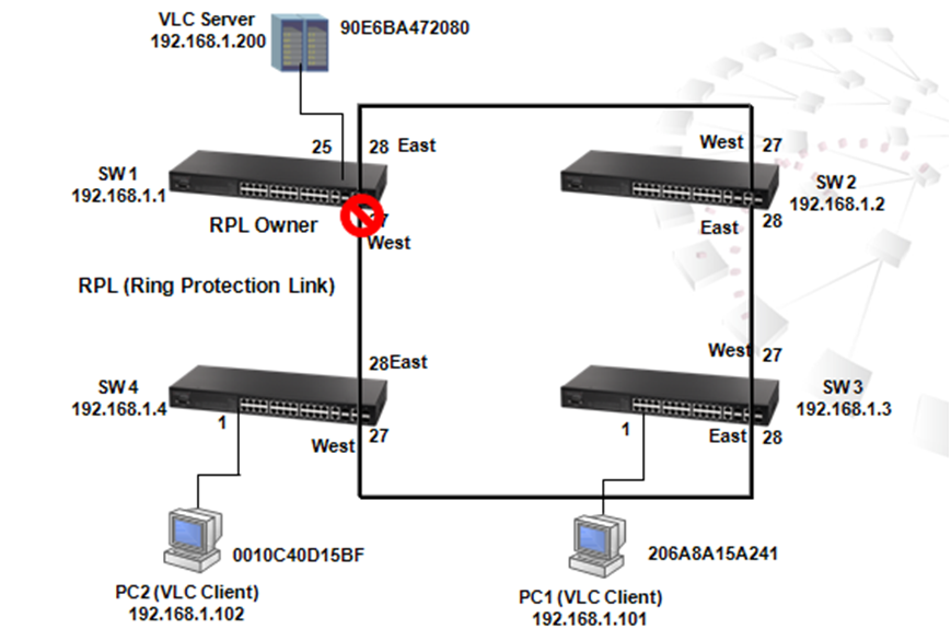
Figure 1
As shown in Figure 1, once ERPS is enabled, SW1 would be RPL owner and sets up a Ring Protection Link to block traffic for preventing loop on bridged ring during IDLE state meanwhile unblocks traffic during Protection state.
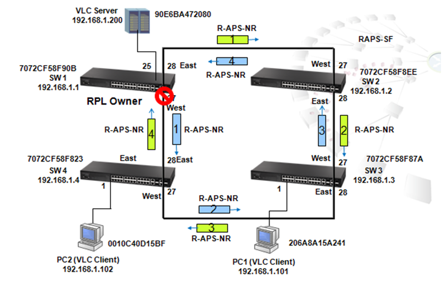
Figure 2
Under IDLE state, Switch 1 sends out Ring Automatic Protection Switch (R-APS) message from its east port (port 28) and west port (port 27) every 5 seconds in order to monitor links in the ring.
Because a loop exists, SW1 receives packet sent from port 27 on port 28, and also receives packet sent out from port 28 on port 27. In order to prevent loop, SW1 blocks the west ring, i.e. port 27.
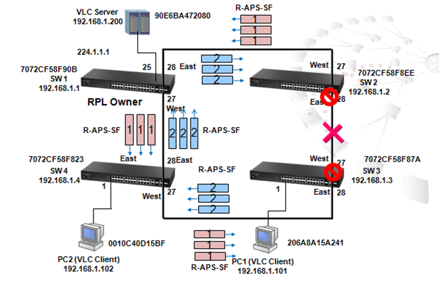
Figure 3
Figure 3 shows a scenario when the link between pot 28 of SW2 and port 27 of SW3 is disconnected. Once the link is disconnected, the port 28 of SW2 and port 27 of SW3 will be blocked, and SW2 and SW3 are into the protection state.
Meanwhile, a "no request" message will be sent out immediately from port 28 of SW3 in order to notice all nodes in the ring to flush the MAC address table.
Also, 3 "Signal Failure" messages are immediately sent out from port 27 of SW2 in order to notice all nodes in the ring to flush the MAC address table.
When SW1 (RPL ) receives the SF message, the mac address table will flush and west ring port 27 will change to forwarding and into Protection mode.
Besides the first "Signal Failure" immediate message sent out while disconnection occures, SW2 will continously send 3 Signal Failure messages every 5 seconds until the connection is repaired as shown in Figure 4.
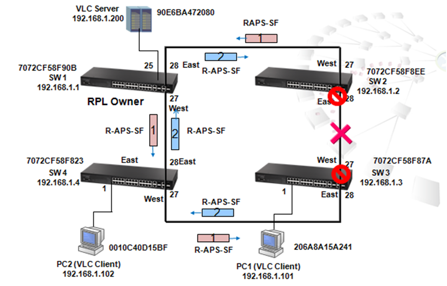
Figure 4
When the link between SW2 pot 28 and SW3 port 27 recovers, the port 28 of SW2 and port 27 of SW3 will remain in blocking state until 5 minutes of wait to restore timer is expired (Figure 9).
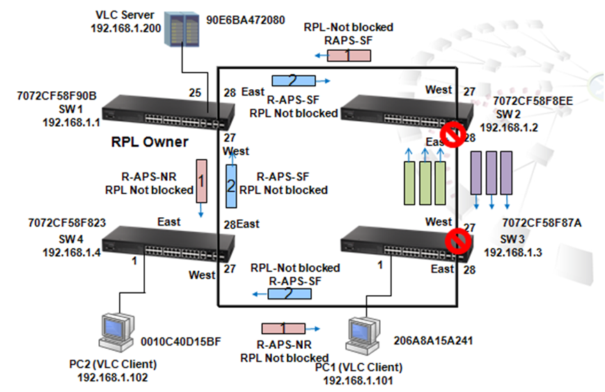
Figure 5
After 5 minutes default WTR (Wait to Restore) timer expires, port 27 (west port) of SW1 (RPL) becomes blocked, 3 "No Request" messages will sent out from port 27 and port 28 of SW1, and every 5 seconds, port 27 and port 28 of SW1 will send out a "No Request" message to routinely report the status of the link in the ring. In the end, port 28 of SW2 and port 27 of SW3 become forwarding and both switches enter IDLE modes.
Received Octets :
1.3.6.1.2.1.31.1.1.1.6 (ifHCInOctets, 64-bit version)
1.3.6.1.2.1.2.2.1.10 (ifInOctets, 32-bit version)
C:\>snmpwalk -v 2c -c private 10.2.28.216 1.3.6.1.2.1.31.1.1.1.6.1
IF-MIB::ifHCInOctets.1 = Counter64: 1751607
C:\>snmpwalk -v 2c -c private 10.2.28.216 1.3.6.1.2.1.2.2.1.10.1
IF-MIB::ifInOctets.1 = Counter32: 1751607
Transmitted Octets :
1.3.6.1.2.1.31.1.1.1.10 (ifHCOutOctets, 64-bit version)
1.3.6.1.2.1.2.2.1.16 (ifOutOctets, 32-bit version)
C:\>snmpwalk -v 2c -c private 10.2.28.216 1.3.6.1.2.1.31.1.1.1.10.1
IF-MIB::ifHCOutOctets.1 = Counter64: 1045353
C:\>snmpwalk -v 2c -c private 10.2.28.216 1.3.6.1.2.1.2.2.1.16.1
IF-MIB::ifOutOctets.1 = Counter32: 1045353
Received Errors :
1.3.6.1.2.1.2.2.1.14 (ifInErrors)
C:\>snmpwalk -v 2c -c private 10.2.28.216 1.3.6.1.2.1.2.2.1.14.1
IF-MIB::ifInErrors.1 = Counter32: 0
Transmitted Errors :
1.3.6.1.2.1.2.2.1.20 (ifOutErrors)
ECS2100 series didn’t support this counter.
C:\>snmpwalk -v 2c -c private 10.2.28.216 1.3.6.1.2.1.2.2.1.20.1
IF-MIB::ifOutErrors.1 = No Such Instance currently exists at this OID
Received Unicast Packets :
1.3.6.1.2.1.31.1.1.1.7 (ifHCInUcastPkts, 64-bit version)
1.3.6.1.2.1.2.2.1.11 (ifInUcastPkts, 32-bit version)
C:\>snmpwalk -v 2c -c private 10.2.28.216 1.3.6.1.2.1.31.1.1.1.7.1
IF-MIB::ifHCInUcastPkts.1 = Counter64: 79
C:\>snmpwalk -v 2c -c private 10.2.28.216 1.3.6.1.2.1.2.2.1.11.1
IF-MIB::ifInUcastPkts.1 = Counter32: 79
Transmitted Unicast Packets :
1.3.6.1.2.1.31.1.1.1.11 (ifHCOutUcastPkts, 64-bit version)
1.3.6.1.2.1.2.2.1.17 (ifOutUcastPkts, 32-bit version)
C:\>snmpwalk -v 2c -c private 10.2.28.216 1.3.6.1.2.1.31.1.1.1.11.1
IF-MIB::ifHCOutUcastPkts.1 = Counter64: 1684
C:\>snmpwalk -v 2c -c private 10.2.28.216 1.3.6.1.2.1.2.2.1.17.1
IF-MIB::ifOutUcastPkts.1 = Counter32: 1684
Received Discarded Packets :
1.3.6.1.2.1.2.2.1.13 (ifInDiscards)
ECS2100 series didn’t support this counter, always return the value as 0.
C:\>snmpwalk -v 2c -c private 10.2.28.216 1.3.6.1.2.1.2.2.1.13.1
IF-MIB::ifInDiscards.1 = Counter32: 0
Transmitted Discarded Packets :
1.3.6.1.2.1.2.2.1.19 (ifOutDiscards)
C:\>snmpwalk -v 2c -c private 10.2.28.216 1.3.6.1.2.1.2.2.1.19.1
IF-MIB::ifOutDiscards.1 = Counter32: 0
Received Multicast Packets :
1.3.6.1.2.1.31.1.1.1.8 (ifHCInMulticastPkts, 64-bit version)
1.3.6.1.2.1.31.1.1.1.2 (ifInMulticastPkts, 32-bit version)
C:\>snmpwalk -v 2c -c private 10.2.28.216 1.3.6.1.2.1.31.1.1.1.8.1
IF-MIB::ifHCInMulticastPkts.1 = Counter64: 20
C:\>snmpwalk -v 2c -c private 10.2.28.216 1.3.6.1.2.1.31.1.1.1.2.1
IF-MIB::ifInMulticastPkts.1 = Counter32: 20
Transmitted Multicast Packets :
1.3.6.1.2.1.31.1.1.1.12 (ifHCOutMulticastPkts, 64-bit version)
1.3.6.1.2.1.31.1.1.1.4 (ifOutMulticastPkts, 32-bit version)
C:\>snmpwalk -v 2c -c private 10.2.28.216 1.3.6.1.2.1.31.1.1.1.12.1
IF-MIB::ifHCOutMulticastPkts.1 = Counter64: 2134
C:\>snmpwalk -v 2c -c private 10.2.28.216 1.3.6.1.2.1.31.1.1.1.4.1
IF-MIB::ifOutMulticastPkts.1 = Counter32: 2134
Received Broadcast Packets :
1.3.6.1.2.1.31.1.1.1.9 (ifHCInBroadcastPkts, 64-bit version)
1.3.6.1.2.1.31.1.1.1.3 (ifInBroadcastPkts, 32-bit version)
C:\>snmpwalk -v 2c -c private 10.2.28.216 1.3.6.1.2.1.31.1.1.1.9.1
IF-MIB::ifHCInBroadcastPkts.1 = Counter64: 18069
C:\>snmpwalk -v 2c -c private 10.2.28.216 1.3.6.1.2.1.31.1.1.1.3.1
IF-MIB::ifInBroadcastPkts.1 = Counter32: 18069
Transmitted Broadcast Packets :
1.3.6.1.2.1.31.1.1.1.13 (ifHCOutBroadcastPkts, 64-bit version)
1.3.6.1.2.1.31.1.1.1.5 (ifOutBroadcastPkts, 32-bit version)
C:\>snmpwalk -v 2c -c private 10.2.28.216 1.3.6.1.2.1.31.1.1.1.13.1
IF-MIB::ifHCOutBroadcastPkts.1 = Counter64: 5833
C:\>snmpwalk -v 2c -c private 10.2.28.216 1.3.6.1.2.1.31.1.1.1.5.1
IF-MIB::ifOutBroadcastPkts.1 = Counter32: 5833
Received Unknown Packets :
1.3.6.1.2.1.2.2.1.15 (ifInUnknownProtos)
ECS2100 series didn’t support this counter.
C:\>snmpwalk -v 2c -c private 10.2.28.216 1.3.6.1.2.1.2.2.1.15.1
IF-MIB::ifInUnknownProtos.1 = No Such Instance currently exists at this OID
QLen Output - the length of the output packet queue (in packets) :
1.3.6.1.2.1.2.2.1.21 (ifOutQLen)
ECS2100 series didn’t support this counter.
C:\>snmpwalk -v 2c -c private 10.2.28.216 1.3.6.1.2.1.2.2.1.21.1
IF-MIB::ifOutQLen.1 = No Such Instance currently exists at this OID
Single Collision Frames :
1.3.6.1.2.1.10.7.2.1.4 (dot3StatsSingleCollisionFrames)
C:\>snmpwalk -v 2c -c private 10.2.28.216 1.3.6.1.2.1.10.7.2.1.4.1
SNMPv2-SMI::transmission.7.2.1.4.1 = Counter32: 0
Multiple Collision Frames :
1.3.6.1.2.1.10.7.2.1.5 (dot3StatsMultipleCollisionFrames)
C:\>snmpwalk -v 2c -c private 10.2.28.216 1.3.6.1.2.1.10.7.2.1.5.1
SNMPv2-SMI::transmission.7.2.1.5.1 = Counter32: 0
Late Collisions :
1.3.6.1.2.1.10.7.2.1.8 (dot3StatsLateCollisions)
C:\>snmpwalk -v 2c -c private 10.2.28.216 1.3.6.1.2.1.10.7.2.1.8.1
SNMPv2-SMI::transmission.7.2.1.8.1 = Counter32: 0
Excessive Collisions :
1.3.6.1.2.1.10.7.2.1.9 (dot3StatsExcessiveCollisions)
C:\>snmpwalk -v 2c -c private 10.2.28.216 1.3.6.1.2.1.10.7.2.1.9.1
SNMPv2-SMI::transmission.7.2.1.9.1 = Counter32: 0
Deferred Transmissions :
1.3.6.1.2.1.10.7.2.1.7 (dot3StatsDeferredTransmissions)
C:\>snmpwalk -v 2c -c private 10.2.28.216 1.3.6.1.2.1.10.7.2.1.7.1
SNMPv2-SMI::transmission.7.2.1.7.1 = Counter32: 0
Frames Too Long :
1.3.6.1.2.1.10.7.2.1.13 (dot3StatsFrameTooLongs)
C:\>snmpwalk -v 2c -c private 10.2.28.216 1.3.6.1.2.1.10.7.2.1.13.1
SNMPv2-SMI::transmission.7.2.1.13.1 = Counter32: 0
Symbol Errors :
1.3.6.1.2.1.10.7.2.1.18 (dot3StatsSymbolErrors)
C:\>snmpwalk -v 2c -c private 10.2.28.216 1.3.6.1.2.1.10.7.2.1.18.1
SNMPv2-SMI::transmission.7.2.1.18.1 = Counter32: 0
Pause Frames Input :
1.3.6.1.2.1.10.7.10.1.3 (dot3InPauseFrames)
C:\>snmpwalk -v 2c -c private 10.2.28.216 1.3.6.1.2.1.10.7.10.1.3.1
SNMPv2-SMI::transmission.7.10.1.3.1 = Counter32: 0
Pause Frames Output :
1.3.6.1.2.1.10.7.10.1.4 (dot3OutPauseFrames)
C:\>snmpwalk -v 2c -c private 10.2.28.216 1.3.6.1.2.1.10.7.10.1.4.1
SNMPv2-SMI::transmission.7.10.1.4.1 = Counter32: 0
Alignment Errors :
1.3.6.1.2.1.10.7.2.1.2 (dot3StatsAlignmentErrors)
ECS2100 series didn’t support this counter.
C:\>snmpwalk -v 2c -c private 10.2.28.216 1.3.6.1.2.1.10.7.2.1.2.1
SNMPv2-SMI::transmission.7.2.1.2.1 = No Such Instance currently exists at this OID
FCS Errors :
1.3.6.1.2.1.10.7.2.1.3 (dot3StatsFCSErrors)
C:\>snmpwalk -v 2c -c private 10.2.28.216 1.3.6.1.2.1.10.7.2.1.3.1
SNMPv2-SMI::transmission.7.2.1.3.1 = Counter32: 0
SQE Test Errors :
1.3.6.1.2.1.10.7.2.1.6 (dot3StatsSQETestErrors)
ECS2100 series didn’t support this counter.
C:\>snmpwalk -v 2c -c private 10.2.28.216 1.3.6.1.2.1.10.7.2.1.6.1
SNMPv2-SMI::transmission.7.2.1.6.1 = No Such Instance currently exists at this OID
Carrier Sense Errors :
1.3.6.1.2.1.10.7.2.1.11 (dot3StatsCarrierSenseErrors)
ECS2100 series didn’t support this counter.
C:\>snmpwalk -v 2c -c private 10.2.28.216 1.3.6.1.2.1.10.7.2.1.11.1
SNMPv2-SMI::transmission.7.2.1.11.1 = No Such Instance currently exists at this OID
Internal MAC Receive Errors :
1.3.6.1.2.1.10.7.2.1.16 (dot3StatsInternalMacReceiveErrors)
ECS2100 series didn’t support this counter.
C:\>snmpwalk -v 2c -c private 10.2.28.216 1.3.6.1.2.1.10.7.2.1.16.1
SNMPv2-SMI::transmission.7.2.1.16.1 = No Such Instance currently exists at this OID
Internal MAC Transmit Errors :
1.3.6.1.2.1.10.7.2.1.10 (dot3StatsInternalMacTransmitErrors)
C:\>snmpwalk -v 2c -c private 10.2.28.216 1.3.6.1.2.1.10.7.2.1.10.1
SNMPv2-SMI::transmission.7.2.1.10.1 = Counter32: 0
Drop Events :
1.3.6.1.2.1.16.1.1.1.3 (etherStatsDropEvents)
C:\>snmpwalk -v 2c -c private 10.2.28.216 1.3.6.1.2.1.16.1.1.1.3.1
SNMPv2-SMI::mib-2.16.1.1.1.3.1 = Counter32: 0
Jabbers :
1.3.6.1.2.1.16.1.1.1.12 (etherStatsJabbers)
C:\>snmpwalk -v 2c -c private 10.2.28.216 1.3.6.1.2.1.16.1.1.1.12.1
SNMPv2-SMI::mib-2.16.1.1.1.12.1 = Counter32: 0
Fragments :
1.3.6.1.2.1.16.1.1.1.11 (etherStatsFragments)
C:\>snmpwalk -v 2c -c private 10.2.28.216 1.3.6.1.2.1.16.1.1.1.11.1
SNMPv2-SMI::mib-2.16.1.1.1.11.1 = Counter32: 0
Collisions :
1.3.6.1.2.1.16.1.1.1.13 (etherStatsCollisions)
C:\>snmpwalk -v 2c -c private 10.2.28.216 1.3.6.1.2.1.16.1.1.1.13.1
SNMPv2-SMI::mib-2.16.1.1.1.13.1 = Counter32: 0
Received Octets :
1.3.6.1.2.1.16.1.1.1.4 (etherStatsOctets)
C:\>snmpwalk -v 2c -c private 10.2.28.216 1.3.6.1.2.1.16.1.1.1.4.1
SNMPv2-SMI::mib-2.16.1.1.1.4.1 = Counter32: 2796960
Received Packets :
1.3.6.1.2.1.16.1.1.1.5 (etherStatsPkts)
C:\>snmpwalk -v 2c -c private 10.2.28.216 1.3.6.1.2.1.16.1.1.1.5.1
SNMPv2-SMI::mib-2.16.1.1.1.5.1 = Counter32: 23320
Broadcast Packets :
1.3.6.1.2.1.16.1.1.1.6 (etherStatsBroadcastPkts)
C:\>snmpwalk -v 2c -c private 10.2.28.216 1.3.6.1.2.1.16.1.1.1.6.1
SNMPv2-SMI::mib-2.16.1.1.1.6.1 = Counter32: 23902
Multicast Packets :
1.3.6.1.2.1.16.1.1.1.7 (etherStatsMulticastPkts)
C:\>snmpwalk -v 2c -c private 10.2.28.216 1.3.6.1.2.1.16.1.1.1.7.1
SNMPv2-SMI::mib-2.16.1.1.1.7.1 = Counter32: 2154
CRC Align Errors :
1.3.6.1.2.1.16.1.1.1.8 (etherStatsCRCAlignErrors)
C:\>snmpwalk -v 2c -c private 10.2.28.216 1.3.6.1.2.1.16.1.1.1.8.1
SNMPv2-SMI::mib-2.16.1.1.1.8.1 = Counter32: 0
Undersize Packets :
1.3.6.1.2.1.16.1.1.1.9 (etherStatsUndersizePkts)
C:\>snmpwalk -v 2c -c private 10.2.28.216 1.3.6.1.2.1.16.1.1.1.9.1
SNMPv2-SMI::mib-2.16.1.1.1.9.1 = Counter32: 0
Oversize Packets :
1.3.6.1.2.1.16.1.1.1.10 (etherStatsOversizePkts)
C:\>snmpwalk -v 2c -c private 10.2.28.216 1.3.6.1.2.1.16.1.1.1.10.1
SNMPv2-SMI::mib-2.16.1.1.1.10.1 = Counter32: 0
64 Byte Packets :
1.3.6.1.2.1.16.1.1.1.14 (etherStatsPkts64Octets)
C:\>snmpwalk -v 2c -c private 10.2.28.216 1.3.6.1.2.1.16.1.1.1.14.1
SNMPv2-SMI::mib-2.16.1.1.1.14.1 = Counter32: 4522
65-127 Byte Packets :
1.3.6.1.2.1.16.1.1.1.15 (etherStatsPkts65to127Octets)
C:\>snmpwalk -v 2c -c private 10.2.28.216 1.3.6.1.2.1.16.1.1.1.15.1
SNMPv2-SMI::mib-2.16.1.1.1.15.1 = Counter32: 21524
128-255 Byte Packets :
1.3.6.1.2.1.16.1.1.1.16 (etherStatsPkts128to255Octets)
C:\>snmpwalk -v 2c -c private 10.2.28.216 1.3.6.1.2.1.16.1.1.1.16.1
SNMPv2-SMI::mib-2.16.1.1.1.16.1 = Counter32: 887
256-511 Byte Packets :
1.3.6.1.2.1.16.1.1.1.17 (etherStatsPkts256to511Octets)
C:\>snmpwalk -v 2c -c private 10.2.28.216 1.3.6.1.2.1.16.1.1.1.17.1
SNMPv2-SMI::mib-2.16.1.1.1.17.1 = Counter32: 827
512-1023 Byte Packets :
1.3.6.1.2.1.16.1.1.1.18 (etherStatsPkts512to1023Octets)
C:\>snmpwalk -v 2c -c private 10.2.28.216 1.3.6.1.2.1.16.1.1.1.18.1
SNMPv2-SMI::mib-2.16.1.1.1.18.1 = Counter32: 53
1024-1518 Byte Packets :
1.3.6.1.2.1.16.1.1.1.19 (etherStatsPkts1024to1518Octets)
C:\>snmpwalk -v 2c -c private 10.2.28.216 1.3.6.1.2.1.16.1.1.1.19.1
SNMPv2-SMI::mib-2.16.1.1.1.19.1 = Counter32: 6
Input Octets in kbits per second :
1.3.6.1.4.1.259.10.1.43.1.2.6.1.2 (portInOctetRate)
C:\>snmpwalk -v 2c -c private 10.2.28.216 1.3.6.1.4.1.259.10.1.43.1.2.6.1.2.1
SNMPv2-SMI::enterprises.259.10.1.43.1.2.6.1.2.1 = Counter64: 0
Input Packets per second :
1.3.6.1.4.1.259.10.1.43.1.2.6.1.3 (portInPacketRate)
C:\>snmpwalk -v 2c -c private 10.2.28.216 1.3.6.1.4.1.259.10.1.43.1.2.6.1.3.1
SNMPv2-SMI::enterprises.259.10.1.43.1.2.6.1.3.1 = Counter64: 0
Input Utilization :
1.3.6.1.4.1.259.10.1.43.1.2.6.1.4 (portInUtil)
C:\>snmpwalk -v 2c -c private 10.2.28.216 1.3.6.1.4.1.259.10.1.43.1.2.6.1.4.1
SNMPv2-SMI::enterprises.259.10.1.43.1.2.6.1.4.1 = INTEGER: 0
Output Octets in kbits per second :
1.3.6.1.4.1.259.10.1.43.1.2.6.1.5 (portOutOctetRate)
C:\>snmpwalk -v 2c -c private 10.2.28.216 1.3.6.1.4.1.259.10.1.43.1.2.6.1.5.1
SNMPv2-SMI::enterprises.259.10.1.43.1.2.6.1.5.1 = Counter64: 0
Output Packets per second :
1.3.6.1.4.1.259.10.1.43.1.2.6.1.6 (portOutPacketRate)
C:\>snmpwalk -v 2c -c private 10.2.28.216 1.3.6.1.4.1.259.10.1.43.1.2.6.1.6.1
SNMPv2-SMI::enterprises.259.10.1.43.1.2.6.1.6.1 = Counter64: 0
Output Utilization :
1.3.6.1.4.1.259.10.1.43.1.2.6.1.7 (portOutUtil)
C:\>snmpwalk -v 2c -c private 10.2.28.216 1.3.6.1.4.1.259.10.1.43.1.2.6.1.7.1
SNMPv2-SMI::enterprises.259.10.1.43.1.2.6.1.7.1 = INTEGER: 0
Why does the switch learn new mac addresses on a port when a user configures one static mac-address on a port, and enables port security and sets max-mac-count as 1?
For example,
Console#con
Console(config)#mac-address-table static 20-6A-8A-1C-96-C1 interface ethernet 1/1 vlan 1
Console(config)#interface ethernet 1/1
Console(config-if)#port security
Console(config-if)#port security max-mac-count 1
Console(config-if)#end
Switch can still learn one mac address when the client injects packets on port1.
Console#show mac-address-table
Interface MAC Address VLAN Type Life Time
--------- ----------------- ---- -------- -----------------
CPU 70-72-CF-C8-56-4F 1 CPU Delete on Reset
Eth 1/ 1 20-6A-8A-1C-96-C0 1 Security Delete on Reset
Eth 1/ 1 20-6A-8A-1C-96-C1 1 Config Permanent
Console#
Solution:
It’s normal behavior of port security max-mac-count. It only limits the dynamic mac address. The static address will still be there.

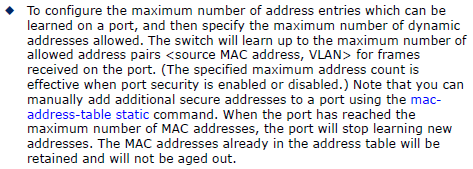
If user does not want to learn any new mac addresses by port security, set the max-mac-count as 0.
Only the incoming traffic with source addresses which are already stored in the static address table will be accepted.
Model: ECS4620 Series, ECS4510 Series (stackable switches)
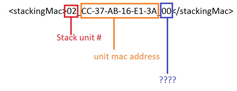
Answer: The field is board id, which is used to identify different board types.
Basically, the privilege's level can be configured from 0 to 15, and we can divide the privilege level into three parts.
- Level 0 to 7 is for the normal user.
- Level 8 to 14 is for the manager. This level cannot configure several functions which belong to level 15. EX: DHCPSNP, IPSG, AAA.
- Level 15 is the top level for the administrator. And, this level can configure all functions of the switch. Also, administrator may add/remove the commands to/from user privilege 0~14.
The version supports ECC (Error correcting code):
ECS4510 Loader version 0.6.0.1 and above
ECS4620 Loader version 0.3.2.1 and above
Environment and Preparation:
- The ECS4620 or ECS4510 switch
- Windows PC(Win7, Win8 or Win10) with one Serial COM port and one RJ45 port
- Download and Unzip Script file
Script for ECS4620 series: ECS4620-28T_uboot_upgrade_v1.0.0.zip
Configuration: Modify config.ini
- [serial] section: Serial COM port
- [tftp]section: tftp client and server's IP address
tftp server is the PC that connect to the ECS4620 or ECS4510, and run the script.
Example:
The PC with Serial COM3 connects to the switch ECS4510-28T console port.
And PC with IP address 192.168.2.150 connect to the switch ECS4510-28T port 1.
Make sure the switch and PC are the same IP subnet.
~~~~~~~~~~~~~~~~~~~~~~~~~~~~~~~~~~~~~~~~~~~~~~~~~~~~~~~~~~~~~~~~~~~~~
File: config.ini
[product]
type = ECS4510-28T
[serial]
port = COM3
[tftp]
client = 192.168.2.20
server = 192.168.2.150
~~~~~~~~~~~~~~~~~~~~~~~~~~~~~~~~~~~~~~~~~~~~~~~~~~~~~~~~~~~~~~~~~~~~~
How to check Serial COM port on the PC?
In Device Manager (Start -> Run -> devemgmt.msc)
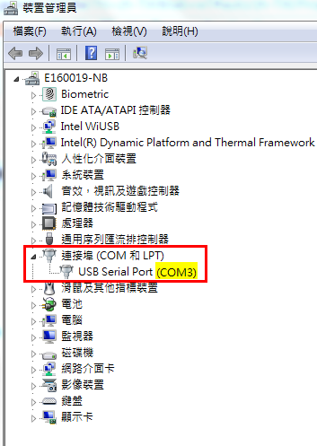
Caution:
- Before running the script, please turn OFF all the terminal on the PC and power OFF the Switch.
- Please make the firewall to allow the TFTP service in order to upgrade successfully
Upgrade loader:
Step 1: Run the script “uboot_upgarde.exe”.
- In CMD (Start -> Execute -> cmd.exe) , enter into the program's folder
- Run uboot_upgrade.exe and .\tftpd32.452\tftpd32.exe will execute automatically
ex:
C:\ECS4510_uboot_upgrade_v0.0.1>uboot_upgrade.exe
- Turn on the power for switch
Step 2: Power ON the switch
After upgrade, uboot_upgrade.exe will close by itself.
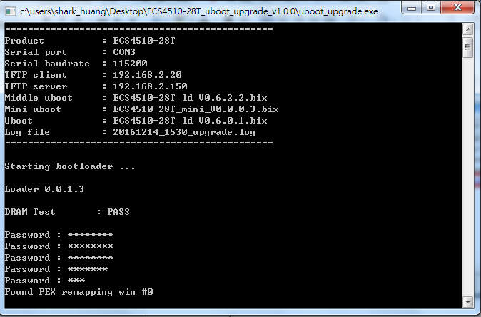
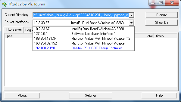
If it fails to upgrade, please send your request and log file to [email protected]
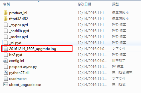
Scenario:
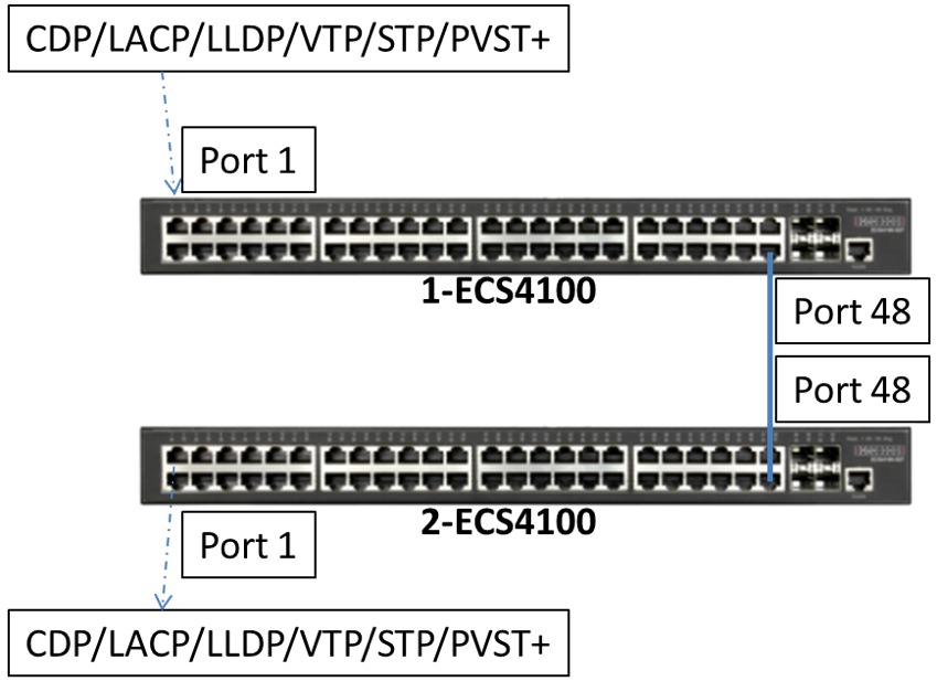
* L2PT can be used to forward CDP/LACP/LLDP/VTP/STP/PVST+ packets.
Procedures:
1. For L2PT to function properly, QinQ must be enabled on the switch.
Console(config)#dot1q-tunnel system-tunnel-control
2. Configure Q-in-Q access port and L2PT on port 1 of 1-ECS4100 and 2-ECS4100. For example: LLDP
Console#configure
Console(config)#interface ethernet 1/1
Console(config-if)#switchport dot1q-tunnel mode access
Console(config-if)#switchport l2protocol-tunnel lldp
3. Configure Q-in-Q uplink port on port 48 of 1-ECS4100 and 2-ECS4100.
Console(config)#interface ethernet 1/48
Console(config-if)#switchport dot1q-tunnel mode uplink
4. Check the status on 1-ECS4100 and 2-ECS4100. Now the both switches will forward LLDP packets.
(receive LLDP packet on the port 1 and forward it to the port 48)
* The switch also replaces the destination MAC address by Tunnel MAC address.
By default, the L2PT MAC address is “01-12-CF-00-00-02” on Edge-corE Switch. Make sure “Tunnel MAC address” is the same on the both switches.
Console#show l2protocol-tunnel
Layer 2 Protocol Tunnel
Tunnel MAC Address : 01-12-CF-00-00-02
Interface Protocol
----------------------------------------------------------
Eth 1/1 LLDP
Console#show dot1q-tunnel
802.1Q Tunnel Status : Enabled
802.1Q Tunnel TPID : 8100 (Hex)
Port Mode Priority Mapping
-------- ------ ----------------
Eth 1/ 1 Access Disabled
Eth 1/48 Uplink Disabled
- What is the Hardware Configuration of ECS4120-28F:
- Front:

- Rear:

- Dual power sources (AC x 1, DC x 1)
- 4 x 10G SFP+ ports (port 25~28)
- 22 x 1G SFP (port 1~22)
- 2 x 1G Combo ports (port 23~24) that support RJ45 and SFP.
- FANLESS design
- Is there any transceiver info (DDM) on 1G SFP port?
Diagnostic Monitoring (DDM).
- Does 1G SFP port support 100M transceiver?
==================================================================
Console#con
Console(config)#int e 1/1
Console(config-if)#exit
Console(config)#interface ethernet 1/1
Console(config-if)#media-type sfp-forced 100fx
Console(config-if)#end
Console#show interfaces status ethernet 1/1
Information of Eth 1/1
Basic Information:
Port Type : 100BASE-FX
MAC Address : 00-E0-0C-00-00-FE
Configuration:
Name :
Port Admin : Up
Speed-duplex : 100full
Capabilities : 100full
Broadcast Storm : Disabled
Broadcast Storm Limit : 500 packets/second
Multicast Storm : Disabled
Multicast Storm Limit : 262143 packets/second
Unknown Unicast Storm : Disabled
Unknown Unicast Storm Limit : 262143 packets/second
Flow Control : Disabled
VLAN Trunking : Disabled
LACP : Disabled
MAC Learning : Enabled
Link-up-down Trap : Enabled
Media Type : SFP forced
MTU : 1518
Current Status:
Link Status : Up
Port Operation Status : Up
Operation Speed-duplex : 100full
Up Time : 0w 0d 0h 0m 26s (26 seconds)
Flow Control Type : None
Max Frame Size : 1518 bytes (1522 bytes for tagged frames)
MAC Learning Status : Enabled
Console#
==================================================================
Notes: New software enhancement is only available for firmware version 1.5.2.7 or above.
Answer:
The default Switch IP address is 192.168.1.1.
To use SNMP OID to modify IP address to 192.168.22.1. Please follow 3 steps:
- Create
- Wait for primary interface
- Active
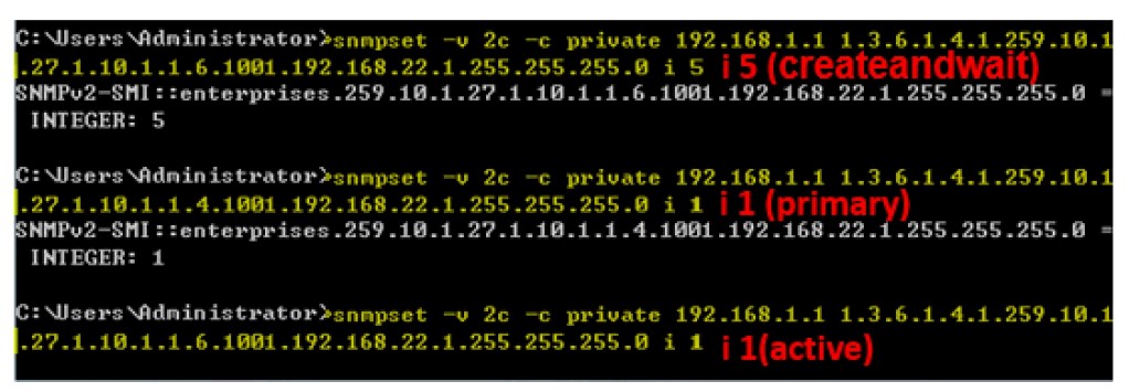
Scenario
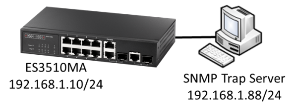
IP Address: 192.168.1.88, UDP Port: 162
Version: v2c
Community String: support
Firmware: ES3510MA v1.5.2.7
MIB requirement: SNMP-NOTIFICATION-MIB, SNMP-TARGET-MIB
ASCII Table reference: http://www.asciitable.com/
A. Configure “snmpNotifyTable”
SNMPSET command format:
snmpset -v 2c -c private <switch ip> < snmpNotifyRowStatus | snmpNotifyTag | snmpNotifyType | snmpNotifyStorageType >.<snmpNotifyName> < INTEGER | STRING > <value>
===Note===
snmpNotifyName index 110.111.116.105.102.121.49(notify1) à Notify Name: notify1
snmpNotifyRowStatus = active(1), notInService(2), notReady(3), createAndGo(4), createAndWait(5), destroy(6)
snmpNotifyType = trap(1), inform(2)
snmpNotifyStorageType = other(1), volatile(2), nonVolatile(3), permanent(4), readOnly(5)
(1) snmpNotifyRowStatus(Integer 5: createAndWait)
C:\>snmpset -v 2c -c private 192.168.1.10 1.3.6.1.6.3.13.1.1.1.5.110.111.116.105.102.121.49 i 5
SNMP-NOTIFICATION-MIB::snmpNotifyRowStatus.'notify1' = INTEGER: createAndWait(5)
(2) snmpNotifyTag(String “trap”)
C:\>snmpset -v 2c -c private 192.168.1.10 1.3.6.1.6.3.13.1.1.1.2.110.111.116.105.102.121.49 s trap
SNMP-NOTIFICATION-MIB::snmpNotifyTag.'notify1' = STRING: trap
(3) snmpNotifyType(Integer 1: trap)
C:\>snmpset -v 2c -c private 192.168.1.10 1.3.6.1.6.3.13.1.1.1.3.110.111.116.105.102.121.49 i 1
SNMP-NOTIFICATION-MIB::snmpNotifyType.'notify1' = INTEGER: trap(1)
(4) snmpNotifyStorageType(Integer 3: nonVolatile)
C:\>snmpset -v 2c -c private 192.168.1.10 1.3.6.1.6.3.13.1.1.1.4.110.111.116.105.102.121.49 i 3
SNMP-NOTIFICATION-MIB::snmpNotifyStorageType.'notify1' = INTEGER: nonVolatile(3)
(5) snmpNotifyRowStatus(Integer 1: active)
C:\>snmpset -v 2c -c private 192.168.1.10 1.3.6.1.6.3.13.1.1.1.5.110.111.116.105.102.121.49 i 1
SNMP-NOTIFICATION-MIB::snmpNotifyRowStatus.'notify1' = INTEGER: active(1)
B. Configure “snmpTargetParamsTable”
SNMPSET command format:
snmpset -v 2c -c private <switch ip> < snmpTargetParamsRowStatus | snmpTargetParamsMPModel | snmpTargetParamsSecurityModel | snmpTargetParamsSecurityName | snmpTargetParamsSecurityLevel | snmpTargetParamsStorageType >.<snmpTargetParamsName> < INTEGER | STRING > <value>
===Note===
snmpTargetParamsName index 112.97.114.97.109.115.49(params1) à Target Parameter Name: params1
snmpTargetParamsRowStatus = active(1), notInService(2), notReady(3), createAndGo(4), createAndWait(5), destroy(6)
snmpTargetParamsMPModel = SNMPv1(0), SNMPv2c(1), SNMPv2u(2), SNMPv3(3), SNMPv2p(256)
snmpTargetParamsSecurityModel = ANY(0), SNMPv1(1), SNMPv2c(2), USM(3), SNMPv2p(256)
snmpTargetParamsSecurityLevel = noAuthNoPriv(1), authNoPriv(2), authPriv(3)
snmpTargetParamsStorageType = other(1), volatile(2), nonVolatile(3), permanent(4), readOnly(5)
(1) snmpTargetParamsRowStatus(Integer 5: createAndWait)
C:\>snmpset -v 2c -c private 192.168.1.10 1.3.6.1.6.3.12.1.3.1.7.112.97.114.97.109.115.49 i 5
SNMP-TARGET-MIB::snmpTargetParamsRowStatus.'params1' = INTEGER: createAndWait(5)
(2) snmpTargetParamsMPModel(Integer 1: SNMPv2c)
C:\>snmpset -v 2c -c private 192.168.1.10 1.3.6.1.6.3.12.1.3.1.2.112.97.114.97.109.115.49 i 1
SNMP-TARGET-MIB::snmpTargetParamsMPModel.'params1' = INTEGER: 1
(3) snmpTargetParamsSecurityModel(Integer 2: SNMPv2c)
C:\>snmpset -v 2c -c private 192.168.1.10 1.3.6.1.6.3.12.1.3.1.3.112.97.114.97.109.115.49 i 2
SNMP-TARGET-MIB::snmpTargetParamsSecurityModel.'params1' = INTEGER: 2
(4) snmpTargetParamsSecurityName(String “support”)
C:\>snmpset -v 2c -c private 192.168.1.10 1.3.6.1.6.3.12.1.3.1.4.112.97.114.97.109.115.49 s support
SNMP-TARGET-MIB::snmpTargetParamsSecurityName.'params1' = STRING: support
(5) snmpTargetParamsSecurityLevel(Integer 1: noAuthNoPriv)
C:\>snmpset -v 2c -c private 192.168.1.10 1.3.6.1.6.3.12.1.3.1.5.112.97.114.97.109.115.49 i 1
SNMP-TARGET-MIB::snmpTargetParamsSecurityLevel.'params1' = INTEGER: noAuthNoPriv(1)
(6) snmpTargetParamsStorageType(Integer 3: nonVolatile)
C:\>snmpset -v 2c -c private 192.168.1.10 1.3.6.1.6.3.12.1.3.1.6.112.97.114.97.109.115.49 i 3
SNMP-TARGET-MIB::snmpTargetParamsStorageType.'params1' = INTEGER: nonVolatile(3)
(7) snmpTargetParamsRowStatus(Integer 1: active)
C:\>snmpset -v 2c -c private 192.168.1.10 1.3.6.1.6.3.12.1.3.1.7.112.97.114.97.109.115.49 i 1
SNMP-TARGET-MIB::snmpTargetParamsRowStatus.'params1' = INTEGER: active(1)
C. Configure “snmpTargetAddrTable”
SNMPSET command format:
snmpset -v 2c -c private <switch ip> < snmpTargetAddrRowStatus | snmpTargetAddrTDomain | snmpTargetAddrTAddress | snmpTargetAddrTagList | snmpTargetAddrParams | snmpTargetAddrStorageType >.<snmpTargetAddrName> < INTEGER | OBJID | HEX STRING | STRING > <value>
===Note===
snmpTargetAddrName index 116.97.114.103.101.116.49(target1) à Target Address Name: target1
snmpTargetAddrRowStatus = active(1), notInService(2), notReady(3), createAndGo(4), createAndWait(5), destroy(6)
snmpTargetAddrTDomain = (1.3.6.1.6.1.1: UDP Domain), (1.3.6.1.6.1.2: CLNS Domain), (1.3.6.1.6.1.3: CONS Domain), (1.3.6.1.6.1.4: DDP Domain), (1.3.6.1.6.1.5: IPX Domain)
snmpTargetAddrTagList = snmpNotifyTag(trap)
snmpTargetAddrParams = snmpTargetParamsName(params1)
snmpTargetAddrStorageType = other(1), volatile(2), nonVolatile(3), permanent(4), readOnly(5)
(1) snmpTargetAddrRowStatus(Integer 5: createAndWait)
C:\>snmpset -v 2c -c private 192.168.1.10 1.3.6.1.6.3.12.1.2.1.9.116.97.114.103.101.116.49 i 5
SNMP-TARGET-MIB::snmpTargetAddrRowStatus.'target1' = INTEGER: createAndWait(5)
(2) snmpTargetAddrTDomain(OBJID 1.3.6.1.6.1.1: UDP Domain)
C:\>snmpset -v 2c -c private 192.168.1.10 1.3.6.1.6.3.12.1.2.1.2.116.97.114.103.101.116.49 o 1.3.6.1.6.1.1
SNMP-TARGET-MIB::snmpTargetAddrTDomain.'target1' = OID: SNMPv2-TM::snmpUDPDomain
(3) snmpTargetAddrTAddress(Hex: C0A8015800A2)
-> C0A80158(192.168.1.88) is IP Address of trap server, 00A2(162) is UDP Port
C:\>snmpset -v 2c -c private 192.168.1.10 1.3.6.1.6.3.12.1.2.1.3.116.97.114.103.101.116.49 x C0A8015800A2
SNMP-TARGET-MIB::snmpTargetAddrTAddress.'target1' = Hex-STRING: C0 A8 01 58 00 A2
(4) snmpTargetAddrTagList(String “trap”)
C:\>snmpset -v 2c -c private 192.168.1.10 1.3.6.1.6.3.12.1.2.1.6.116.97.114.103.101.116.49 s trap
SNMP-TARGET-MIB::snmpTargetAddrTagList.'target1' = STRING: trap
(5) snmpTargetAddrParams(String “params1”)
C:\>snmpset -v 2c -c private 192.168.1.10 1.3.6.1.6.3.12.1.2.1.7.116.97.114.103.101.116.49 s params1
SNMP-TARGET-MIB::snmpTargetAddrParams.'target1' = STRING: params1
(6) snmpTargetAddrStorageType(Integer 3: nonVolatile)
C:\>snmpset -v 2c -c private 192.168.1.10 1.3.6.1.6.3.12.1.2.1.8.116.97.114.103.101.116.49 i 3
SNMP-TARGET-MIB::snmpTargetAddrStorageType.'target1' = INTEGER: nonVolatile(3)
(7) snmpTargetAddrRowStatus(Integer 1: active)
C:\>snmpset -v 2c -c private 192.168.1.10 1.3.6.1.6.3.12.1.2.1.9.116.97.114.103.101.116.49 i 1
SNMP-TARGET-MIB::snmpTargetAddrRowStatus.'target1' = INTEGER: active(1)
Check the configuration on switch.
Console#show snmp
SNMP Logging: Enabled
Logging to 192.168.1.88 support version 2c udp-port 162
Console#
Scenario:
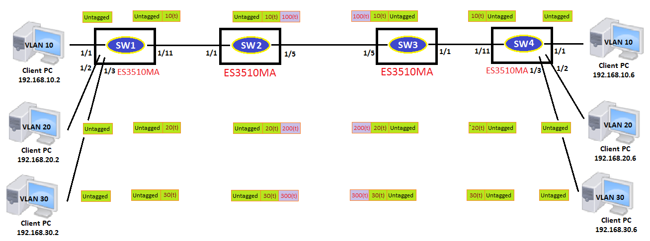
Configuration procedures:
(Start with factory default)
1. Enable QinQ
Console(config)#dot1q-tunnel system-tunnel-control
2. Create vlans
Console(config)#vlan database
Console(config-vlan)#vlan 100,200,300 media ethernet state active
3. Configure Q-in-Q access port
Console(config)#interface ethernet 1/1
Console(config-if)#switchport dot1q-tunnel mode access
Console(config-if)#switchport allowed vlan add 100,200,300 untagged
Console(config-if)#switchport allowed vlan add 10,20,30 tagged
Console(config-if)#switchport dot1q-tunnel service 100 match cvid 10
Console(config-if)#switchport dot1q-tunnel service 200 match cvid 20
Console(config-if)#switchport dot1q-tunnel service 300 match cvid 30
4. Configure Q-in-Q uplink port
Console(config)#interface ethernet 1/5
Console(config-if)#switchport dot1q-tunnel mode uplink
Console(config-if)#switchport allowed vlan add 100,200,300 tagged
At SW1 and SW4:
1. Create vlans
Console(config)#vlan database
Console(config-vlan)#vlan 10,20,30 media ethernet state active
2. Configure access ports
Console(config)#interface ethernet 1/1
Console(config-if)#switchport mode access
Console(config-if)#switchport native vlan 10
Console(config-if)#switchport allowed vlan remove 1
Console(config)#interface ethernet 1/2
Console(config-if)#switchport mode access
Console(config-if)#switchport native vlan 20
Console(config-if)#switchport allowed vlan remove 1
Console(config)#interface ethernet 1/3
Console(config-if)#switchport mode access
Console(config-if)#switchport native vlan 30
Console(config-if)#switchport allowed vlan remove 1
3. Configure trunk port
Console(config)#interface ethernet 1/11
Console(config-if)#switchport mode trunk
Console(config-if)#switchport allowed vlan add 10,20,30 tagged
Console(config-if)#switchport allowed vlan remove 1
Result:
Check the status on SW2 and SW3:
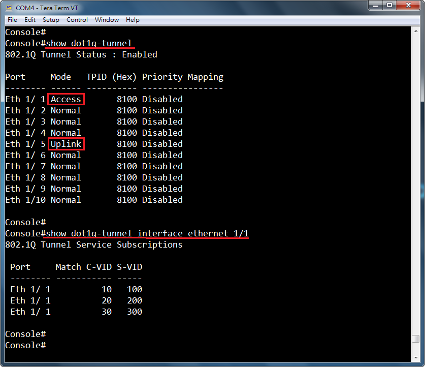
Check the status on SW1 ~ SW4:
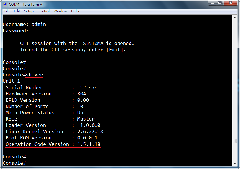
At QinQ tunnel:
Capture packets by WireShark
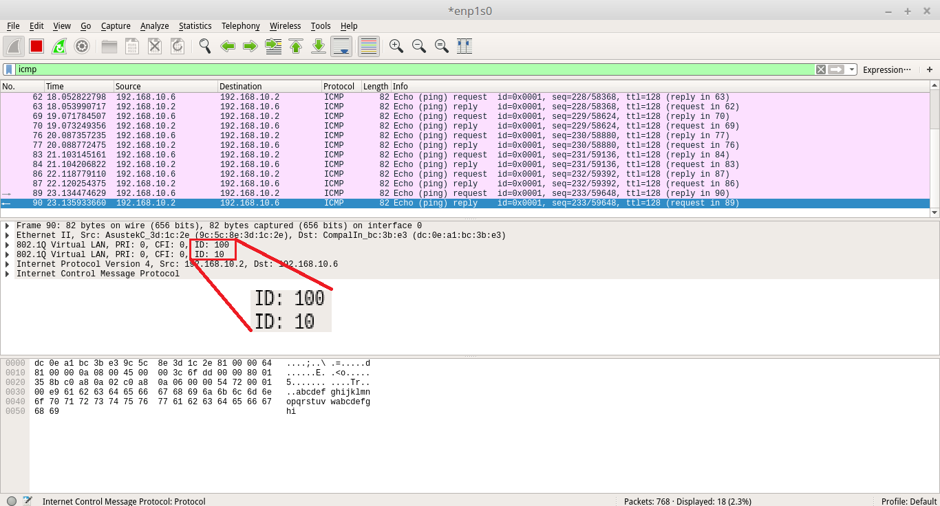
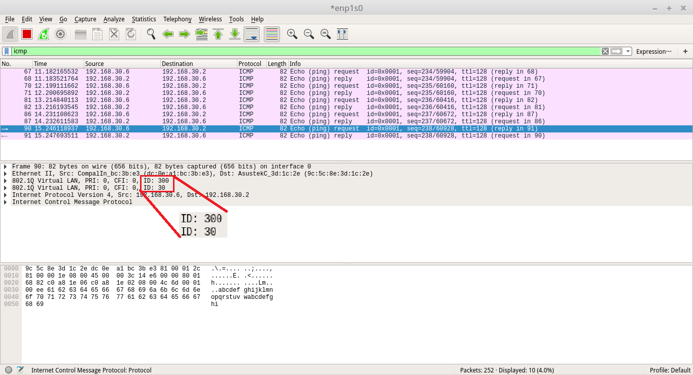
Support Model: ECS4620 Series, ECS3528MV2
Scenario:
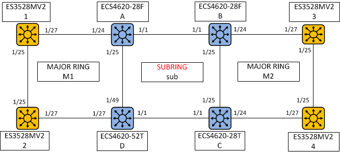
Major Ring M1 is composed of ECS4620-28F A, ECS4620-52T D, ES3528MV2 1 and ES3528MV2 2.
SUBRING sub is composed of ECS4620-28F A, ECS4620-28F B, ECS4620-28T C and ECS4620-52T D.
Major Ring M2 is composed of ECS4620-28F B, ECS4620-28T C, ES3528MV2 3 and ES3528MV2 4.
Configuration procedures:
1. Specify Control VLAN for each ERPS ring first (M1, M2 and sub).
M1 VLAN 10
sub VLAN 20
M2 VLAN 30
2. Add control VLAN to the ring ports, and disable spanning-tree protocol on the ring ports.
3. Assign a switch to be RPL owner for each ERPS ring (M1, M2 and sub) then specifies the west and east port on each switches.
4. Enable the ERPS function.
<1> Major Ring “M1”
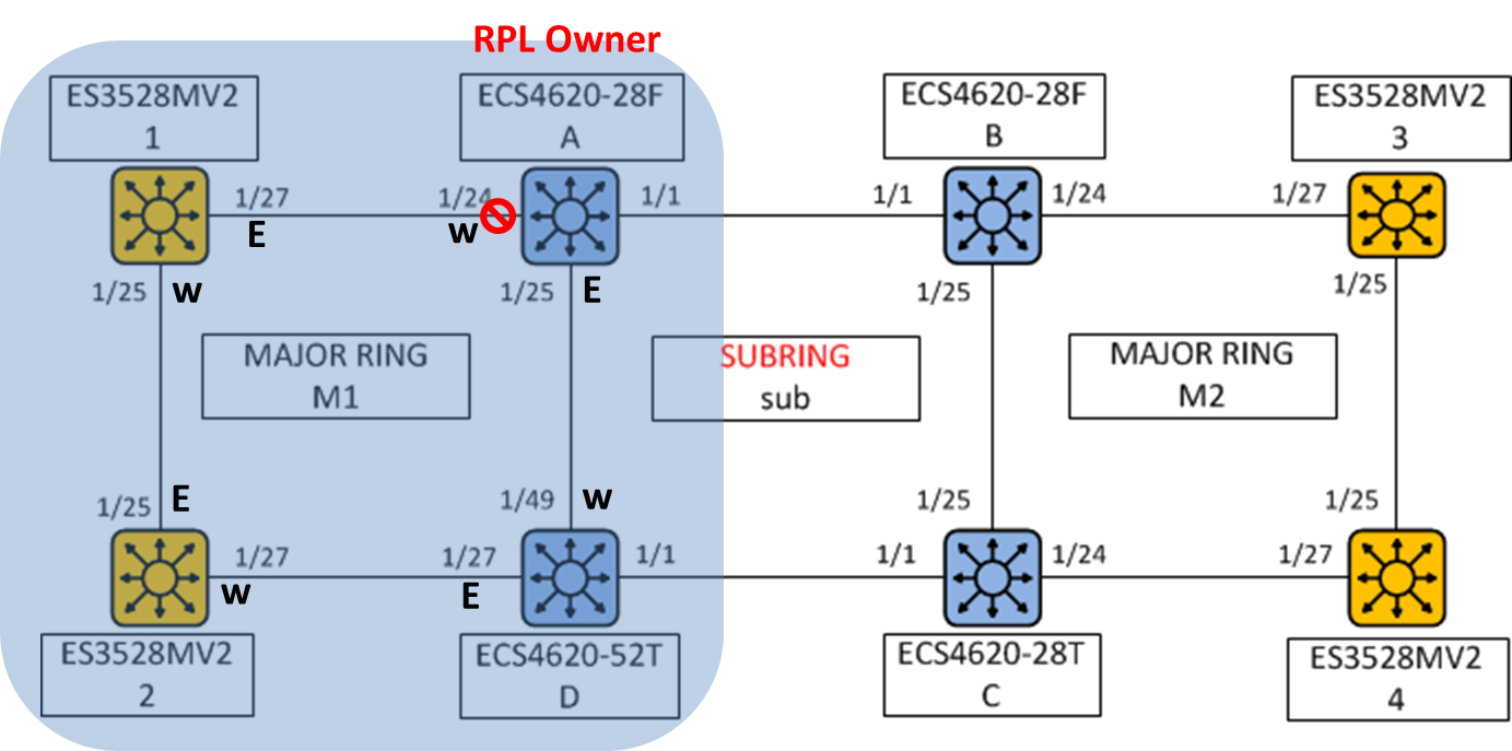
*Control VLAN of M1 ring is VLAN 10.
*RPL Owner of M1 is ECS4620-28F A.
Configuration of major ring “M1”:
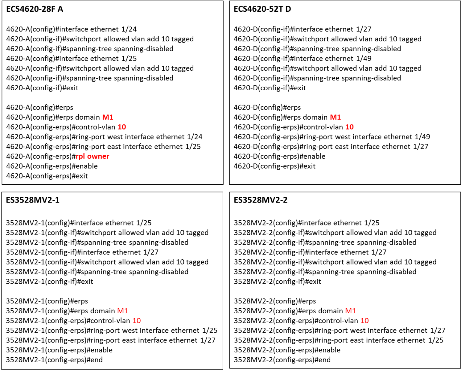
<2> Major Ring “M2”
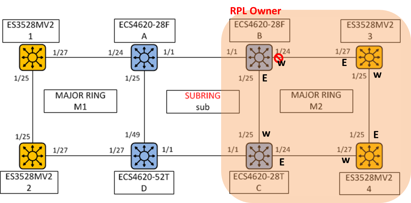
*Control VLAN of M2 ring is VLAN 30.
*RPL Owner of M2 is ECS4620-28F B.
Configuration of major ring “M2”:

<3> Sub Ring “sub”
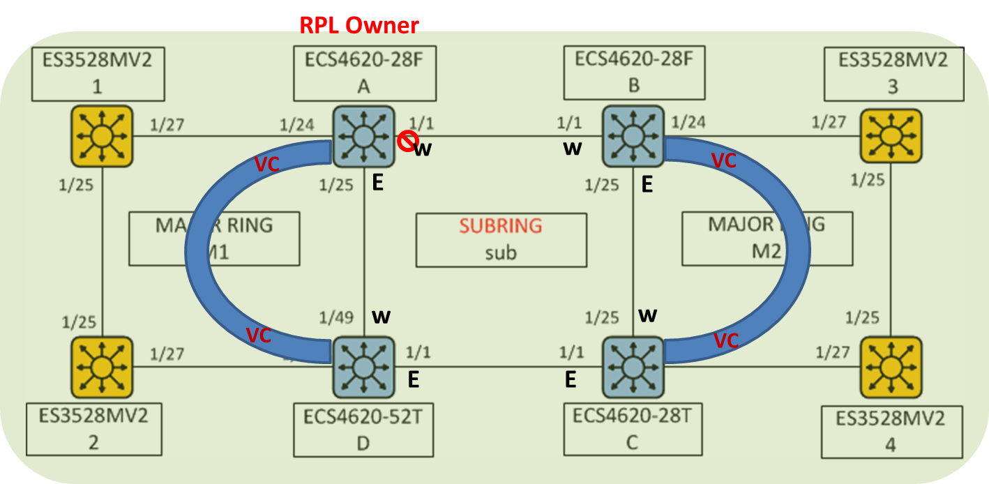
*Control VLAN of sub ring is VLAN 20.
*RPL Owner of sub is ECS4620-28F A.
VC is the Virtual Channel that's used to pass through R-APS message packet of sub-ring.
In other words, user MUST add control VLAN of subring to each ring ports of Major ring (M1 and M2).
Configuration of sub ring “sub”:

The result of ERPS on each switch:
The state will display “Idle” when the network of ring is stable. Please also refer to each of the above ring's topology.
ECS4620-28F A
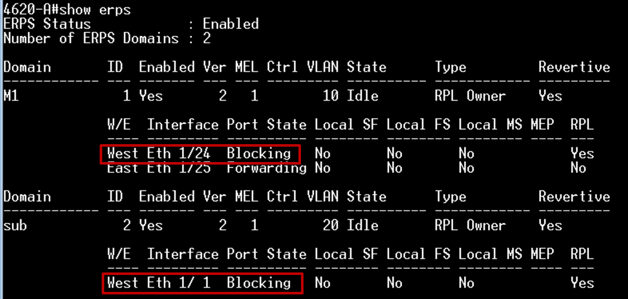
ECS4620-28F B
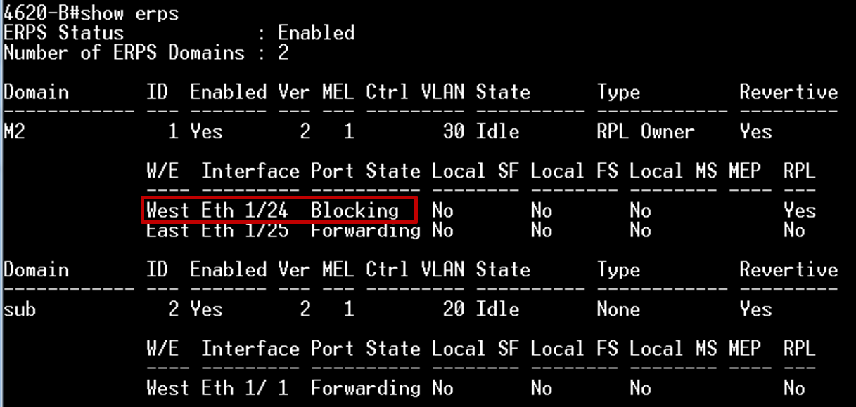
ECS4620-28T C
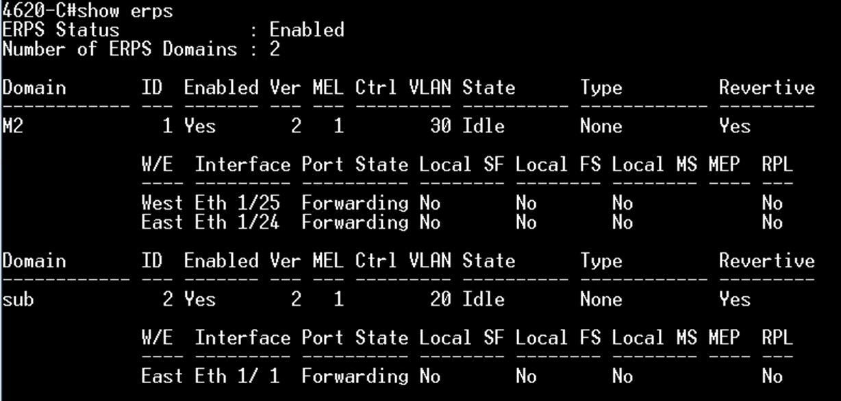
ECS4620-52T D
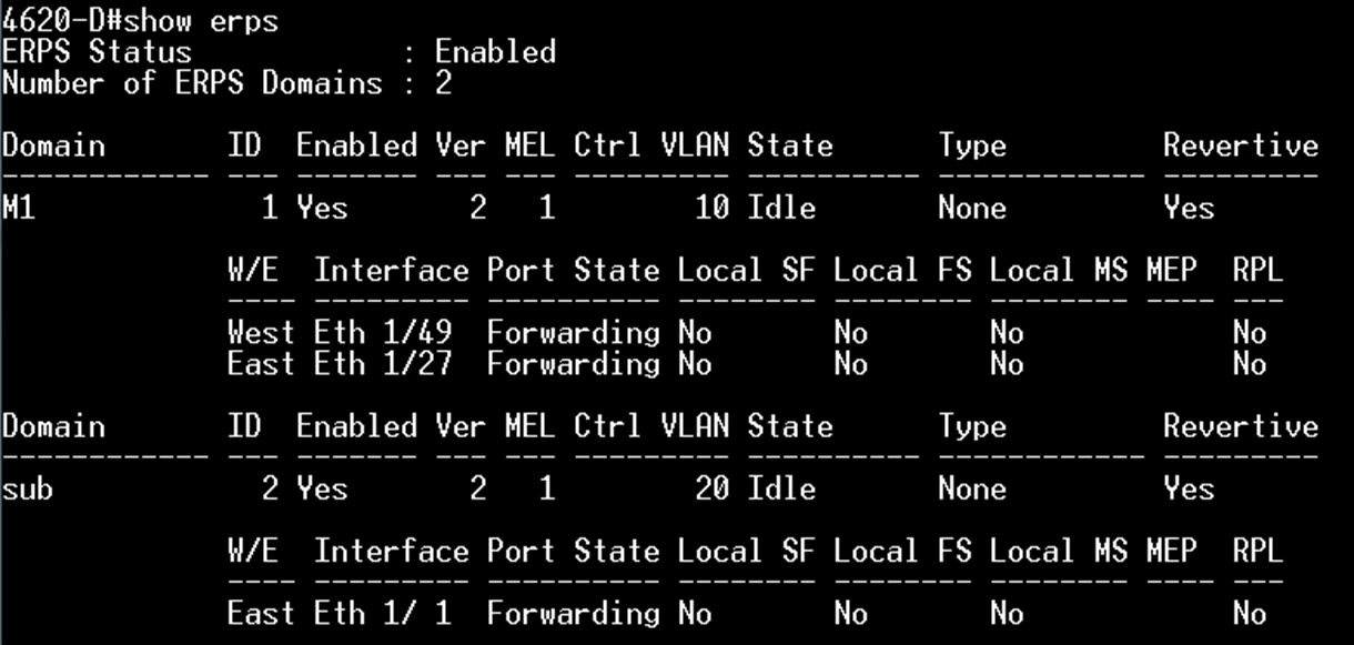
ES3528MV2-1
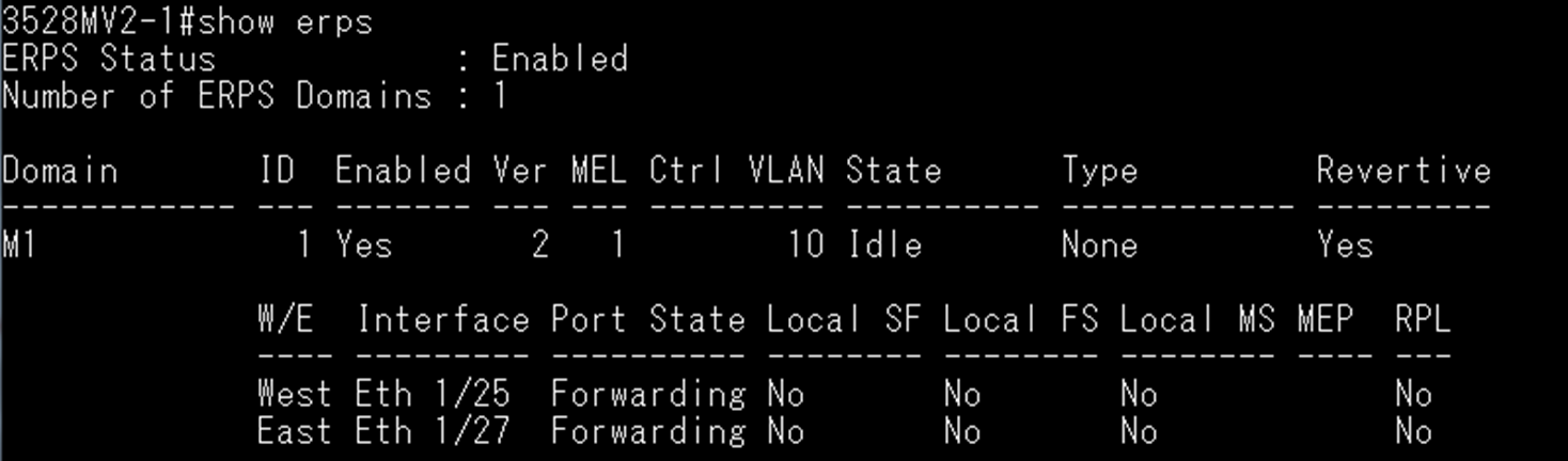
ES3528MV2-2
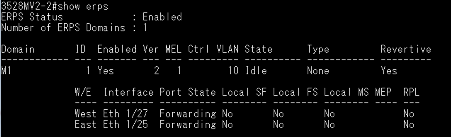
ES3528MV2-3
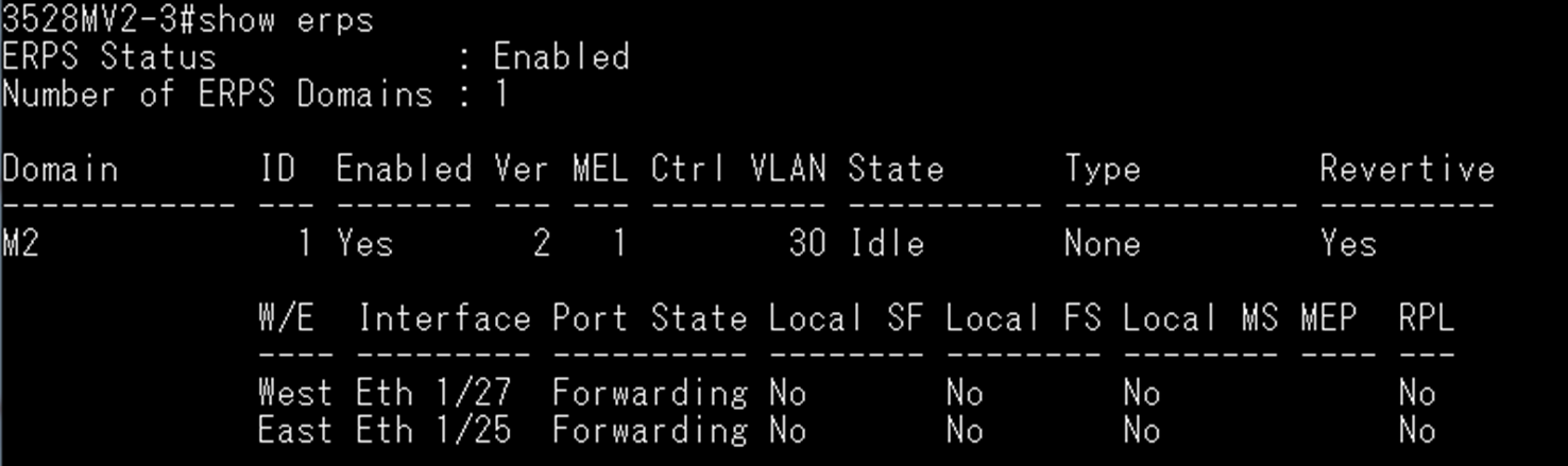
ES3528MV2-4
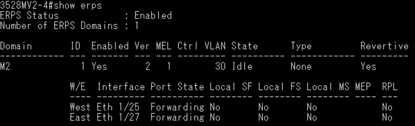
Topology:
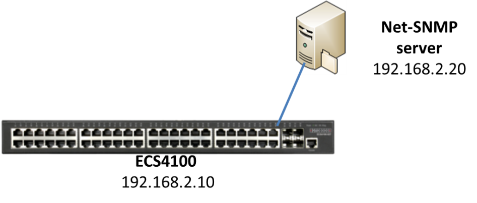
The OID - “fileCopyServerInetAddress”, is used to set the IP address for remote file server.
1. The customer needs to configure the OID - “fileCopyServerInetAddressType” first, which the address type will use the IPv4(1).
fileCopyServerInetAddressType OID = 1.3.6.1.4.1.259.10.1.46.1.24.1.20.0
Command: snmpset -v 2c -c private 192.168.2.10 1.3.6.1.4.1.259.10.1.46.1.24.1.20.0 i 1

2. Then customer will be able to configure the OID - “fileCopyServerInetAddress”.
fileCopyServerInetAddress OID = 1.3.6.1.4.1.259.10.1.46.1.24.1.21.0
Command : snmpset -v 2c -c private 192.168.2.10 1.3.6.1.4.1.259.10.1.46.1.24.1.21.0 x C0A80214

* The IP address needs to be converted to hexadecimal, for example: C0A80214 = 192.168.2.20.
If the customer cannot finish the first step, then the customer would not be able to process to the second step, and will receive an error message.

Client B will get IP (192.168.3.X/24) from DHCP Server.
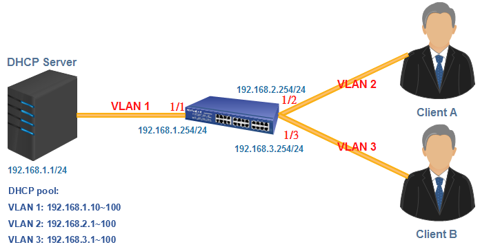
The steps to configure on ECS4620 Series:
Console#configure
Console(config)#interface ethernet 1/2
Console(config-if)#switchport native vlan 2
Console(config-if)#switchport mode access
Console(config-if)#exit
Console(config)#interface ethernet 1/3
Console(config-if)#switchport native vlan 3
Console(config-if)#switchport mode access
Console(config-if)#exit
Console(config)#interface vlan 1
Console(config-if)#ip address 192.168.1.254/24
Console(config)#interface vlan 2
Console(config-if)#ip address 192.168.2.254/24
Console(config-if)#ip dhcp relay server 192.168.1.1
Console(config-if)#exit
Console(config)#interface vlan 3
Console(config-if)#ip address 192.168.3.254/24
Console(config-if)#ip dhcp relay server 192.168.1.1
You can check the setting by using “show ip interface” command.
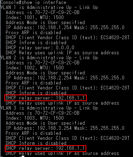
Here’s the result of Client A.
Client A can get the IP from DHCP Server (192.168.1.1)
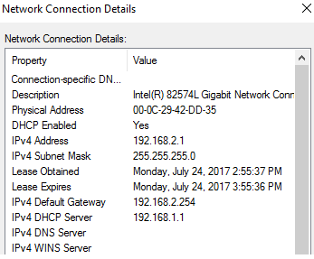
Ports can be grouped into an aggregate link (i.e. trunk) to increase the bandwidth of a network connection or to ensure the fault recovery.
There are two methods to establish this aggregate link in Edgecore switch.
- By manually (aka Static trunks)
- Automatically negotiate a trunk link between the switch and another network device by linking Aggregation Control Protocol (LACP). (aka Dynamic trunks)
If you want to assign specific number, you need to use the admin-key.
Guideline:
• Admin-key available range : 0 – 65535
• Ports are only allowed to join the same trunk if the admin-key match the value.
(The value of admin-key is not important, and the most important thing is to use the same value for matching.)
• By default, the actor’s operational key is determined by port's link speed
(1G -> 4, 100M -> 3, 10M -> 2, Not Detected -> 1), and copied to the admin-key.
Example:
Use admin-key to assign port-channel number on ECS4120-28T.
Topology:

Firmware version:
ECS2100-10T → v1.2.2.0
ECS4120-28T → v1.0.2.20
Procedures:
Step 1. Start with factory default configuration.
Step 2. Use LACP to create port-channel.
@ ECS2100-10T
2100# configure
2100(config)# interface ethernet 1/1,2
2100(config-if)# lacp
@ ECS4120-28T
4120# configure
4120(config)# interface ethernet 1/1,2
4120(config-if)# lacp
Step 3. Check port-channel status on both ECS4120-28T and ECS2100-10T
(By default, port-channel number ID is 1)
@ ECS4120-28T
4120# show interface brief
Interface Name Status PVID Pri Speed/Duplex Type Trunk
--------- ----------------- --------- ---- --- ------------- ------------ -----
Eth 1/ 1 Up 1 0 Auto-1000full 1000BASE-T 1
Eth 1/ 2 Up 1 0 Auto-1000full 1000BASE-T 1
…
…
Eth 1/27 Down 1 0 10Gfull 10GBASE SFP+ None
Eth 1/28 Down 1 0 10Gfull 10GBASE SFP+ None
Trunk 1 Up 1 0 Auto-1000full 1000BASE-T 1
4120# show interface status port-channel 1
Information of Trunk 1
Basic Information:
Port Type : 1000BASE-T
MAC Address : 8C-EA-1B-23-D8-44
Configuration:
Name :
Port Admin : Up
Speed-duplex : Auto
Capabilities : 10half, 10full, 100half, 100full, 1000full
…
…
Current Status:
Created By : LACP
Link Status : Up
Port Operation Status : Up
Operation Speed-duplex : 1000full
Up Time : 0w 0d 0h 1m 23s (83 seconds)
Flow Control Type : None
Max Frame Size : 1518 bytes (1522 bytes for tagged frames)
MAC Learning Status : Enabled
Member Ports : Eth1/1, Eth1/2
Active Member Ports : Eth1/1, Eth1/2
@ ECS2100-10T
2100# show interface brief
Interface Name Status PVID Pri Speed/Duplex Type Trunk
--------- ----------------- --------- ---- --- ------------- ------------ -----
Eth 1/ 1 Up 1 0 Auto-1000full 1000BASE-T 1
Eth 1/ 2 Up 1 0 Auto-1000full 1000BASE-T 1
…
…
Eth 1/27 Down 1 0 10Gfull 10GBASE SFP+ None
Eth 1/28 Down 1 0 10Gfull 10GBASE SFP+ None
Trunk 1 Up 1 0 Auto-1000full 1000BASE-T 1
2100# show interface status port-channel 1
Information of Trunk 1
Basic Information:
Port Type : 1000BASE-T
MAC Address : CC-37-AB-54-F2-38
Configuration:
Name :
Port Admin : Up
Speed-duplex : Auto
Capabilities : 10half, 10full, 100half, 100full, 1000full
…
…
Current Status:
Created By : LACP
Link Status : Up
Port Operation Status : Up
Operation Speed-duplex : 1000full
Up Time : 0w 0d 0h 1m 47s (107 seconds)
Flow Control Type : None
Max Frame Size : 1518 bytes (1522 bytes for tagged frames)
MAC Learning Status : Enabled
Member Ports : Eth1/1, Eth1/2
Active Member Ports : Eth1/1, Eth1/2
Step 4. Use admin-key to assign port-channel number on ECS4120-28T.
(change port-channel ID from 1 to 2)
Create port-channel 2 manually and assign admin-key to the port-channel 2 interface.
Set the same admin-key to its member ports. (port 1 & port 2)
@ ECS4120-28T
4120(config)# int port-channel 2
4120(config-if)# lacp admin-key 20
4120(config-if)# exit
4120(config)# interface ethernet 1/1,2
4120(config-if)# lacp actor admin-key 20
Step 5. Wait for a while and check port-channel status on ECS4120-28T
@ ECS4120-28T
4120# show interface brief
Interface Name Status PVID Pri Speed/Duplex Type Trunk
--------- ----------------- --------- ---- --- ------------- ------------ -----
Eth 1/ 1 Up 1 0 Auto-1000full 1000BASE-T 2
Eth 1/ 2 Up 1 0 Auto-1000full 1000BASE-T 2
…
…
Eth 1/27 Down 1 0 10Gfull 10GBASE SFP+ None
Eth 1/28 Down 1 0 10Gfull 10GBASE SFP+ None
Trunk 2 Up 1 0 Auto-1000full 1000BASE-T 2
4120# show interface status port-channel 2
Information of Trunk 2
Basic Information:
Port Type : 1000BASE-T
MAC Address : 8C-EA-1B-23-D8-44
Configuration:
Name :
Port Admin : Up
Speed-duplex : Auto
Capabilities : 10half, 10full, 100half, 100full, 1000full
…
…
Current Status:
Created By : LACP
Link Status : Up
Port Operation Status : Up
Operation Speed-duplex : 1000full
Up Time : 0w 0d 0h 5m 59s (359 seconds)
Flow Control Type : None
Max Frame Size : 1518 bytes (1522 bytes for tagged frames)
MAC Learning Status : Enabled
Member Ports : Eth1/1, Eth1/2
Active Member Ports : Eth1/1, Eth1/2
4120# show lacp internal
Port Channel : 1
Admin Key : 0
Oper Key : 0
Timeout : Long
Port Channel : 2
Admin Key : 20
Oper Key : 20
Timeout : Long
…
…
sFlow, short for "sampled flow".
- sFlow is an industry standard provided by a wide range of network equipment and software application vendors.
- sFlow provides a network-wide view of usage and active routes. It is a scalable technique for measuring network traffic, collecting, storing, and analyzing traffic data. This enables tens of thousands of interfaces to be monitored from a single location.
Topology:
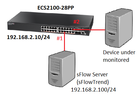
At the ECS2100 series, this feature is a new enhancement on phase 2 firmware. (v1.2.2.0 and above.)
Here is the sample showing how to configure sFlow on ECS2100-28PP.
Switch's Configuration:
- Configure the management IP address on switch.
Console(config)# interface vlan 1
Console(config-if)# ip address 192.168.2.10/24
- Create a sFlow owner and specific the destination IP address.
- The allowed range of timeout: 30 – 10000000 sec
- It supports the following sFlow versions: v4 / v5
- Specific the monitored port and the receiver.
- The allowed range of the sampling-rate: 2 – 65535
When the sampling-rate is bigger, the sampling will be slower.
- Check the sFlow status.
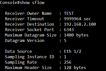
sFlowTrend:
You can download it for free from the official website:
http://www.inmon.com/products/sFlowTrend.php
After installation, add the switch agent which you want to manage.
Then you can see the statistic graph to the monitored port.
You can also use the filter to find the data that you want.
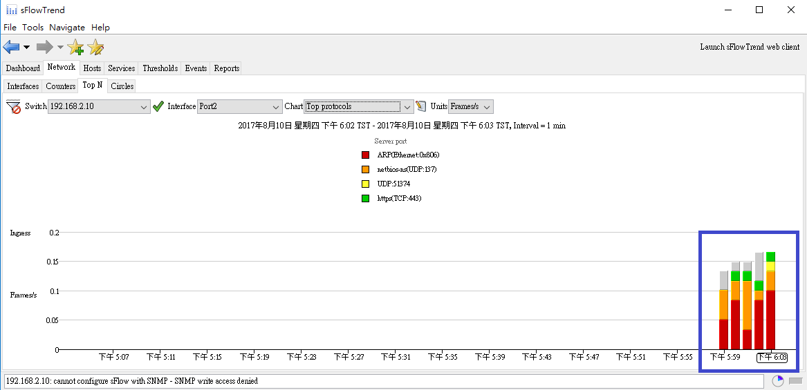

Configuration example:

- Enable DHCP snooping on global mode and VLAN.
Console(config)#ip dhcp snooping
Console(config)#ip dhcp snooping vlan 1
- Enable the DHCP Option 82 information.
- Specify the DHCP snooping trust port.
Console(config-if)#ip dhcp snooping trust
- Check the status of DHCP snooping.

- When the switch receives the DHCP packets from the client, the DHCP packets will be added the option 82 information. (capture packet on port 2 aka Eth 1/2)
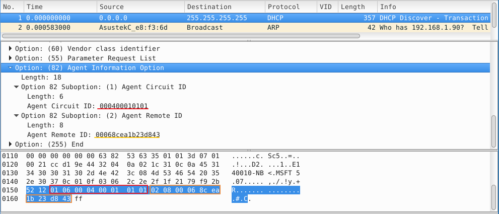
Additional example:
By default, the Remote-ID is MAC address. You can change the type of Remote-ID to switch’s IP address.

Console(config)#interface vlan 1
Console(config-if)#ip address 1.1.1.1/24
Console(config)#ip dhcp snooping
Console(config)#ip dhcp snooping vlan 1
Console(config)#ip dhcp snooping information option remote-id ip-address
Console(config)#interface ethernet 1/2
Console(config-if)#ip dhcp snooping trust
The switch will insert an IP address in the remote ID sub-option on the DHCP packet of the client.
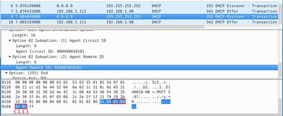
Models: ECS4620 series, ECS4510 series, ECS4120 series, ECS4100 series, ECS4110 series, ECS4210 series, ECS3510-28T/52T, ES3528Mv2, ES3510MA, ECS2100 series
ARP Table OID:
ipNetToMediaIfIndex:1.3.6.1.2.1.4.22.1.1
ipNetToMediaPhysAddress:1.3.6.1.2.1.4.22.1.2
ipNetToMediaNetAddress:1.3.6.1.2.1.4.22.1.3
ipNetToMediaType:1.3.6.1.2.1.4.22.1.4
For example:
.png)
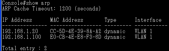
ipNetToMediaIfIndex:1.3.6.1.2.1.4.22.1.1
C:\Documents and Settings\Administrator>snmpwalk.exe -v 2c -c private 192.168.1.1
1.3.6.1.2.1.4.22.1.1
IP-MIB::ipNetToMediaIfIndex.1001.192.168.1.20 = INTEGER: 1001
IP-MIB::ipNetToMediaIfIndex.1001.192.168.1.100 = INTEGER: 1001
※Note – The value of '1001' indicates the VLAN 1 in Edgecore switch.
ipNetToMediaPhysAddress:1.3.6.1.2.1.4.22.1.2
C:\Documents and Settings\Administrator>snmpwalk.exe -v 2c -c private 192.168.1.1
1.3.6.1.2.1.4.22.1.2
IP-MIB::ipNetToMediaPhysAddress.1001.192.168.1.20 = STRING: cc:5d:4e:39:8a:a2
IP-MIB::ipNetToMediaPhysAddress.1001.192.168.1.100 = STRING: e0:cb:4e:e8:f3:6d
ipNetToMediaNetAddress:1.3.6.1.2.1.4.22.1.3
C:\Documents and Settings\Administrator>snmpwalk.exe -v 2c -c private 192.168.1.1
1.3.6.1.2.1.4.22.1.3
IP-MIB::ipNetToMediaNetAddress.1001.192.168.1.20 = IpAddress: 192.168.1.20
IP-MIB::ipNetToMediaNetAddress.1001.192.168.1.100 = IpAddress: 192.168.1.100
ipNetToMediaType:1.3.6.1.2.1.4.22.1.4
C:\Documents and Settings\Administrator>snmpwalk.exe -v 2c -c private 192.168.1.1
1.3.6.1.2.1.4.22.1.4
IP-MIB::ipNetToMediaType.1001.192.168.1.20 = INTEGER: dynamic(3)
IP-MIB::ipNetToMediaType.1001.192.168.1.100 = INTEGER: dynamic(3)
※Value list - 1: other(1), 2: invalid(2), 3: dynamic(3), 4: static(4)
Mac Address Table OID:
dot1dTpFdbAddress:1.3.6.1.2.1.17.4.3.1.1
dot1dTpFdbPort:1.3.6.1.2.1.17.4.3.1.2
dot1dTpFdbStatus:1.3.6.1.2.1.17.4.3.1.3
For example:
.png)
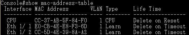
dot1dTpFdbAddress:1.3.6.1.2.1.17.4.3.1.1
C:\usr\bin>snmpwalk.exe -v 2c -c private 192.168.1.1 1.3.6.1.2.1.17.4.3.1.1
SNMPv2-SMI::mib-2.17.4.3.1.1.204.55.171.95.132.240 = Hex-STRING: CC 37 AB 5F 84 F0
SNMPv2-SMI::mib-2.17.4.3.1.1.204.93.78.57.138.162 = Hex-STRING: CC 5D 4E 39 8A A2
SNMPv2-SMI::mib-2.17.4.3.1.1.224.203.78.232.243.109 = Hex-STRING: E0 CB 4E E8 F3 6D
dot1dTpFdbPort:1.3.6.1.2.1.17.4.3.1.2
C:\usr\bin>snmpwalk.exe -v 2c -c private 192.168.1.1 1.3.6.1.2.1.17.4.3.1.2
SNMPv2-SMI::mib-2.17.4.3.1.2.204.55.171.95.132.240 = INTEGER: 0
SNMPv2-SMI::mib-2.17.4.3.1.2.204.93.78.57.138.162 = INTEGER: 2
SNMPv2-SMI::mib-2.17.4.3.1.2.224.203.78.232.243.109 = INTEGER: 1
※Note – This value indicates the port number of switch, and the value of '0' is switch own MAC address.
dot1dTpFdbStatus:1.3.6.1.2.1.17.4.3.1.3
C:\usr\bin>snmpwalk.exe -v 2c -c private 192.168.1.1 1.3.6.1.2.1.17.4.3.1.3
SNMPv2-SMI::mib-2.17.4.3.1.3.204.55.171.95.132.240 = INTEGER: 4
SNMPv2-SMI::mib-2.17.4.3.1.3.204.93.78.57.138.162 = INTEGER: 3
SNMPv2-SMI::mib-2.17.4.3.1.3.224.203.78.232.243.109 = INTEGER: 3
※Value list - 1: other(1), 2: invalid(2), 3: learned(3), 4: self(4), 5: mgmt(5)
Network topology and switch configurations as shown below:
Hint:
The connections (blue line) between the switch A, B, C, D belong to ERPS major-ring.
The connections (orange line) between the switch C, D, E, F belong to ERPS sub-ring.
.png)
Major Ring (Domain): Switch A is RPL Owner for major ring.
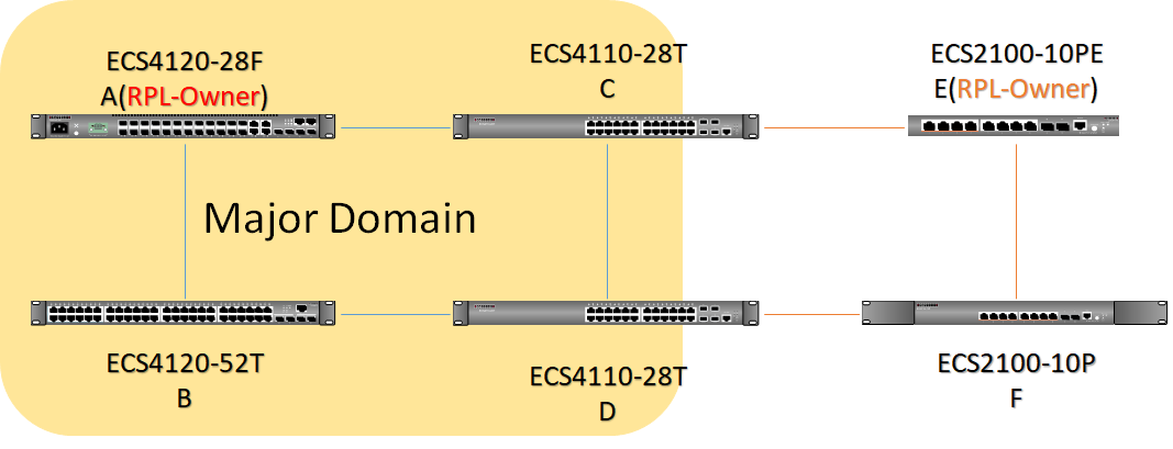
Sub Ring (Domain): Switch E is RPL Owner for sub ring.
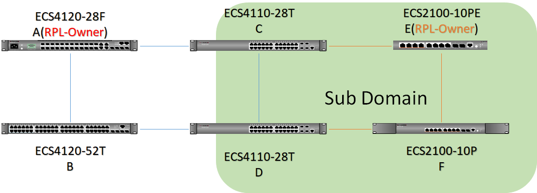
Blocking port
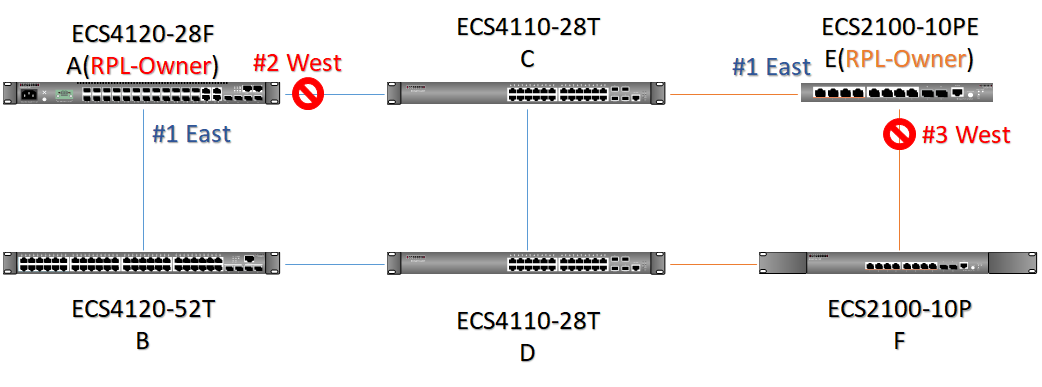
Default Status
A
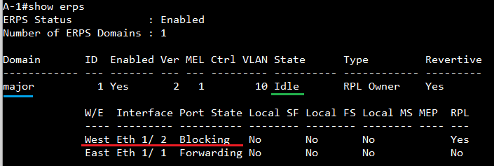
B
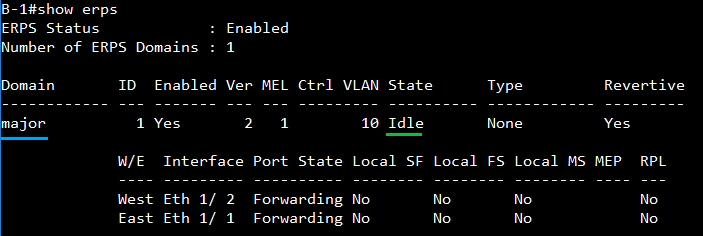
C
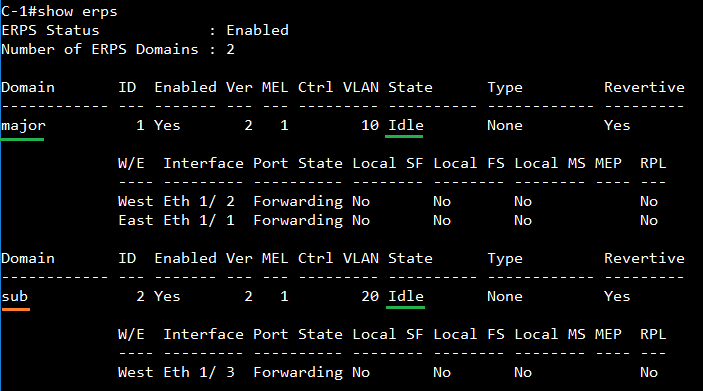
D
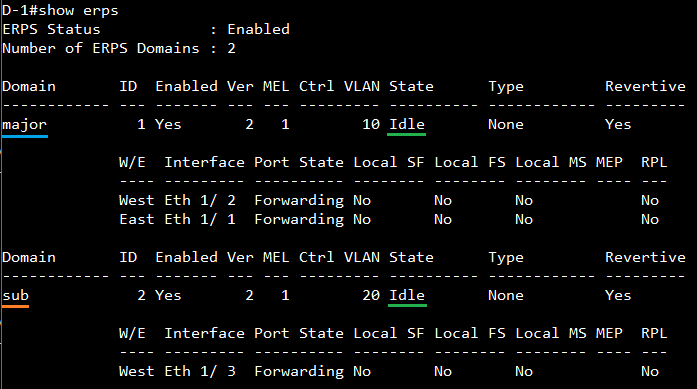
E
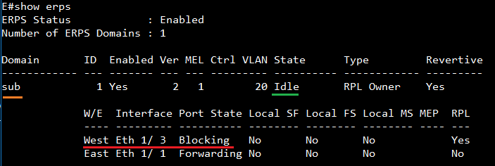
F
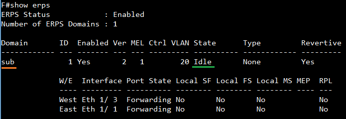
If there is a link failure in sub-ring, the state of blocking port of sub-ring may change from blocking to forwarding.
Hint: The connections (orange line) between the switch C, D, E, F belong to ERPS sub-ring.
For example: The link between switch C and E is disconnected. The port 3 of switch E (RPL-Owner for sub-ring) will change state from blocking to forwarding.
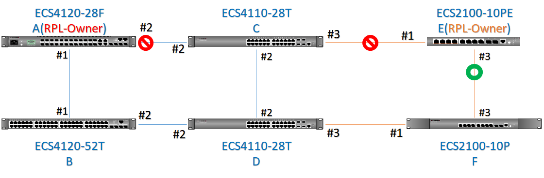
Meanwhile, the state of Sub-Domain will change from Idle to Protection.
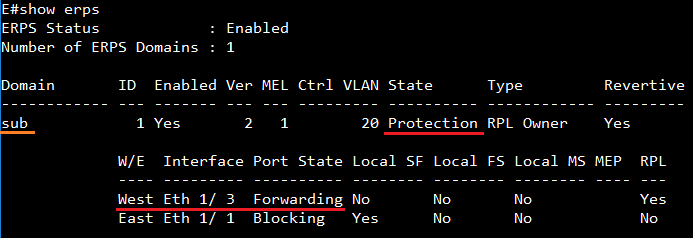
If there is a link failure in major-ring, the status of sub-ring will not change.
Hint:
The connections (blue line) between the switch A, B, C, D belong to ERPS major-ring.
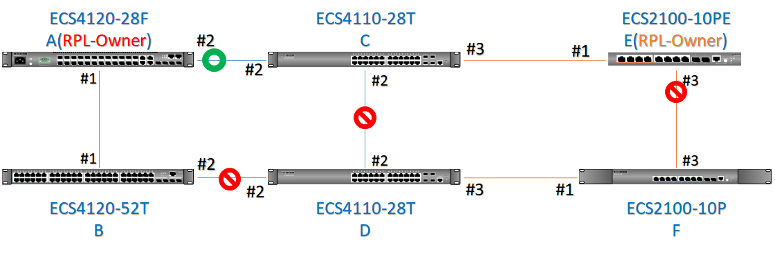
For example: Links between switch C and D, Switch B and D) are disconnected, but blocking port of sub-ring is still at blocking state. The state of sub-ring is still “Idle”.
The status of Sub-Domain does not change. And port 3 of switch E is still blocking.
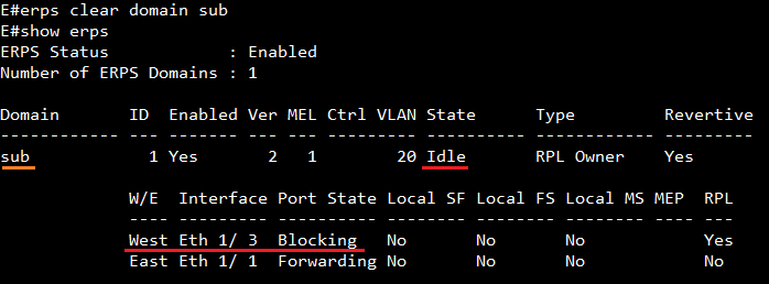
ECS4100 series fileCopyMgt OID: 1.3.6.1.4.1.259.10.1.46.1.24.1
ECS4120 series fileCopyMgt OID: 1.3.6.1.4.1.259.10.1.45.1.24.1
ECS4510 series fileCopyMgt OID: 1.3.6.1.4.1.259.10.1.24.1.24.1
ECS4110 series fileCopyMgt OID: 1.3.6.1.4.1.259.10.1.39.1.24.1
ECS4210 series fileCopyMgt OID: 1.3.6.1.4.1.259.10.1.42.101.1.24.1
ES3510MA fileCopyMgt OID: 1.3.6.1.4.1.259.8.1.11.1.24.1
ECS3510-28T, 52T fileCopyMgt OID: 1.3.6.1.4.1.259.10.1.27.1.24.1
ES3528MV2 fileCopyMgt OID: 1.3.6.1.4.1.259.10.1.22.1.24.1
ECS2100 series fileCopyMgt OID: 1.3.6.1.4.1.259.10.1.43.1.24.1
ECS4620 series fileCopyMGt OID: 1.3.6.1.4.1.259.10.1.41.1.24.1
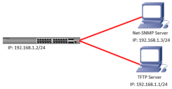
Download the file via SNMP. (Below the sample is for ECS2100 series)
Step 1: specifies where to copy from.
C:\Users\Administrator\Desktop>snmpset -v 2c -c private 192.168.1.2
1.3.6.1.4.1.259.10.1.43.1.24.1.1.0 i 1
SNMPv2-SMI::enterprises.259.10.1.43.1.24.1.1.0 = INTEGER: 1
192.168.1.2 switch's IP
1.3.6.1.4.1.259.10.1.43.1.24.1.1.0 means fileCopySrcOperType
i 1: file(1) indicates switch’s file.
Step 2: specifies source file name.
C:\Users\Administrator\Desktop>snmpset -v 2c -c private 192.168.1.2
1.3.6.1.4.1.259.10.1.43.1.24.1.2.0 s test_ECS2100.cfg
SNMPv2-SMI::enterprises.259.10.1.43.1.24.1.2.0 = STRING: "test_ECS2100.cfg"
1.3.6.1.4.1.259.10.1.43.1.24.1.2.0 means fileCopySrcFileName
s test_ECS2100.cfg : source file name
Step 3: specifies where to copy to.
C:\Users\Administrator\Desktop>snmpset -v 2c -c private 192.168.1.2
1.3.6.1.4.1.259.10.1.43.1.24.1.3.0 i 4
SNMPv2-SMI::enterprises.259.10.1.43.1.24.1.3.0 = INTEGER: 4
1.3.6.1.4.1.259.10.1.43.1.24.1.3.0 means fileCopyDestOperType
i 4: tftp(4) If you want to file copy to FTP server, you should choose 7.
Step 4: specifies destination file name.
C:\Users\Administrator\Desktop>snmpset -v 2c -c private 192.168.1.2
1.3.6.1.4.1.259.10.1.43.1.24.1.4.0 s test_ECS2100.cfg
SNMPv2-SMI::enterprises.259.10.1.43.1.24.1.4.0 = STRING: "test_ECS2100.cfg"
1.3.6.1.4.1.259.10.1.43.1.24.1.4.0 means fileCopyDestFileName
s test_ECS2100.cfg : destinatoin file name
Step 5: specifies file type.
C:\Users\Administrator\Desktop>snmpset -v 2c -c private 192.168.1.2
1.3.6.1.4.1.259.10.1.43.1.24.1.5.0 i 2
SNMPv2-SMI::enterprises.259.10.1.43.1.24.1.5.0 = INTEGER: 2
1.3.6.1.4.1.259.10.1.43.1.24.1.5.0 means fileCopyFileType
i 2: config (2) ---> indicates configuration file.
If you want to download the firmware, please specify to 1.
Step 6: specifies internet address type.
C:\Users\Administrator\Desktop>snmpset -v 2c -c private 192.168.1.2
1.3.6.1.4.1.259.10.1.43.1.24.1.20.0 i 1
SNMPv2-SMI::enterprises.259.10.1.43.1.24.1.20.0 = INTEGER: 1
1.3.6.1.4.1.259.10.1.43.1.24.1.20.0 means fileCopyServerInetAddressType
i 1: ipv4 (1) --> internet address type of the remote server
Step 7: specifies Server’s IP.
C:\Users\Administrator\Desktop>snmpset -v 2c -c private 192.168.1.2
1.3.6.1.4.1.259.10.1.43.1.24.1.21.0 x C0A80101
SNMPv2-SMI::enterprises.259.10.1.43.1.24.1.21.0 = Hex-STRING: C0 A8 01 01
1.3.6.1.4.1.259.10.1.43.1.24.1.21.0 means fileCopyServerInetAddress
x C0A80101: TFTP Server’s IP need in hexadecimal.
You can convert your IP to hexadecimal via this link.
http://ncalculators.com/digital-computation/ip-address-hex-decimal-binary.htm
Step 8: begin the copy operation.
C:\Users\Administrator\Desktop>snmpset -v 2c -c private 192.168.1.2
1.3.6.1.4.1.259.10.1.43.1.24.1.8.0 i 2
SNMPv2-SMI::enterprises.259.10.1.43.1.24.1.8.0 = INTEGER: 2
1.3.6.1.4.1.259.10.1.43.1.24.1.8.0 means fileCopyAction
i 2: copy (2)---> setting this object to begin the copy operation.
Upload the file via SNMP.
Step 1: specifies where to copy from.
C:\Users\Administrator\Desktop>snmpset -v 2c -c private 192.168.1.2
1.3.6.1.4.1.259.10.1.43.1.24.1.1.0 i 4
SNMPv2-SMI::enterprises.259.10.1.43.1.24.1.1.0 = INTEGER: 4
1.3.6.1.4.1.259.10.1.43.1.24.1.1.0 means fileCopySrcOperType
i 4: tftp(4) If you want to upload the file via FTP server, you should choose 7.
Step 2: specifies source file name.
C:\Users\Administrator\Desktop>snmpset -v 2c -c private 192.168.1.2
1.3.6.1.4.1.259.10.1.43.1.24.1.2.0 s test_ECS2100.cfg
SNMPv2-SMI::enterprises.259.10.1.43.1.24.1.2.0 = STRING: "test_ECS2100.cfg"
1.3.6.1.4.1.259.10.1.43.1.24.1.2.0 means fileCopySrcFileName
s test_ECS2100.cfg : source file name
Step 3: specifies where to copy to.
C:\Users\Administrator\Desktop>snmpset -v 2c -c private 192.168.1.2
1.3.6.1.4.1.259.10.1.43.1.24.1.3.0 i 1
SNMPv2-SMI::enterprises.259.10.1.43.1.24.1.3.0 = INTEGER: 1
1.3.6.1.4.1.259.10.1.43.1.24.1.3.0 means fileCopyDestOperType
i 1: file(1) indicates switch’s file.
Step 4: specifies destination file name.
C:\Users\Administrator\Desktop>snmpset -v 2c -c private 192.168.1.2
1.3.6.1.4.1.259.10.1.43.1.24.1.4.0 s test_ECS2100.cfg
SNMPv2-SMI::enterprises.259.10.1.43.1.24.1.4.0 = STRING: "test_ECS2100.cfg"
1.3.6.1.4.1.259.10.1.43.1.24.1.4.0 means fileCopyDestFileName
s test_ECS2100.cfg : destinatoin file name
Step 5: specifies file type.
C:\Users\Administrator\Desktop>snmpset -v 2c -c private 192.168.1.2
1.3.6.1.4.1.259.10.1.43.1.24.1.5.0 i 2
SNMPv2-SMI::enterprises.259.10.1.43.1.24.1.5.0 = INTEGER: 2
1.3.6.1.4.1.259.10.1.43.1.24.1.5.0 means fileCopyFileType
i 2: config (2) ---> indicates configuration file.
If you want to upload the firmware, please specify to 1.
Step 6: specifies internet address type.
C:\Users\Administrator\Desktop>snmpset -v 2c -c private 192.168.1.2
1.3.6.1.4.1.259.10.1.43.1.24.1.20.0 i 1
SNMPv2-SMI::enterprises.259.10.1.43.1.24.1.20.0 = INTEGER: 1
1.3.6.1.4.1.259.10.1.43.1.24.1.20.0 means fileCopyServerInetAddressType
i 1: ipv4 (1) --> internet address type of the remote server
Step 7: specifies Server’s IP.
C:\Users\Administrator\Desktop>snmpset -v 2c -c private 192.168.1.2
1.3.6.1.4.1.259.10.1.43.1.24.1.21.0 x C0A80101
SNMPv2-SMI::enterprises.259.10.1.43.1.24.1.21.0 = Hex-STRING: C0 A8 01 01
1.3.6.1.4.1.259.10.1.43.1.24.1.21.0 means fileCopyServerInetAddress
x C0A80101: TFTP Server’s IP need in hexadecimal.
You can convert your IP to hexadecimal via this link.
http://ncalculators.com/digital-computation/ip-address-hex-decimal-binary.htm
Step 8: begin the copy operation.
C:\Users\Administrator\Desktop>snmpset -v 2c -c private 192.168.1.2
1.3.6.1.4.1.259.10.1.43.1.24.1.8.0 i 2
SNMPv2-SMI::enterprises.259.10.1.43.1.24.1.8.0 = INTEGER: 2
1.3.6.1.4.1.259.10.1.43.1.24.1.8.0 means fileCopyAction
i 2: copy (2)---> setting this object to begin the copy operation.
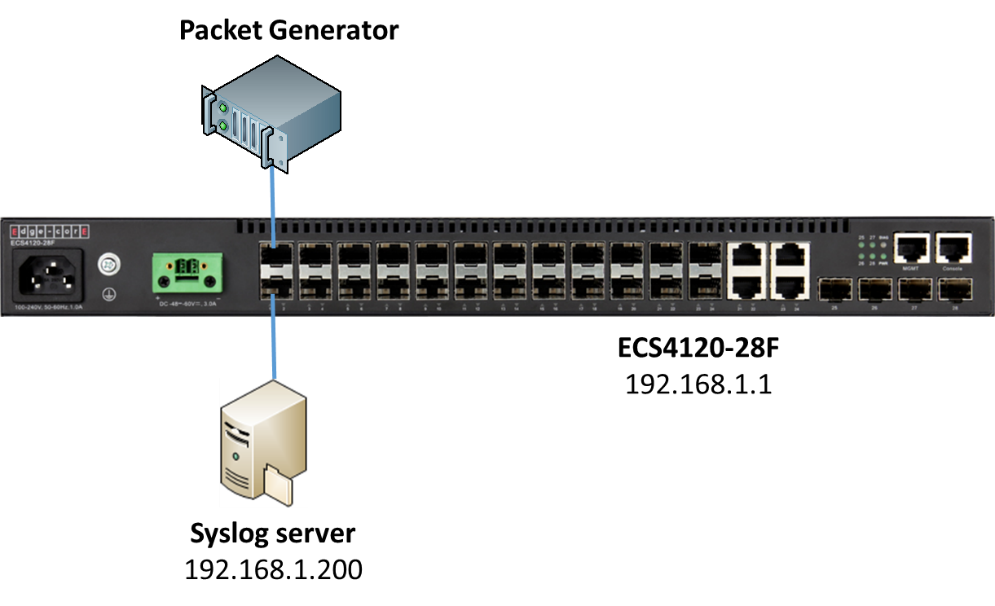
Firmware version: V.1.0.2.29
Behavior of ATC:
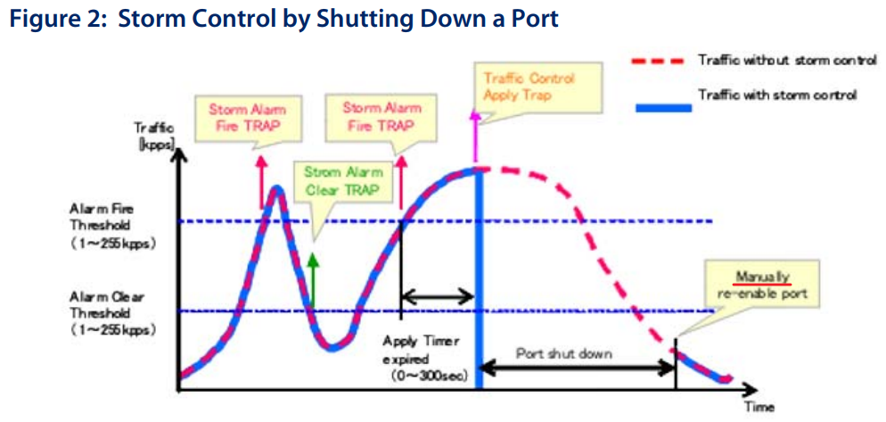
Notice: the port need to be re-enabled manually when it is shut down by ATC.
Procedures:
<1> Configure the IP address of syslog server on switch and enable the “trap” function. (Please remember to configure the management IP address on switch first.)
Console(config)#logging host 192.168.1.200
Console(config)#logging trap
Console#show logging trap
Global Configuration:
Syslog Logging : Enabled
Remote Logging Configuration:
Status : Enabled
Facility Type : Local use 7 (23)
Level Type : Debugging messages (7)
Remote Host 1 :
Server IP Address : 192.168.1.200
Port : 514
<2> Configure the ATC function for broadcast/multicast traffic. (The following is an example for broadcast, and the configuration method is the same for multicast.)
- Setup the apply-timer, the timer will start to countdown when the traffic trigger the fire-threshold.
If the traffic does not reduce to the clear-threshold before the end of the countdown, switch will active the control action to limit ingress traffic or shut down the offending port.
- Setup the “shutdown” action of ATC and enable the trap function for it.
Console(config-if)#auto-traffic-control broadcast action shutdown
Console(config-if)#snmp-server enable port-traps atc broadcast-control-apply
- Configure the fire-threshold and enable the trap function for it.
Notice: The fire-threshold cannot lower then clear-threshold.
Notice: The unit of ATC-threshold is “Kilo-packets per second”. For example: If you configure 200 then the threshold will be 200,000 pps (200*1,000).
Console(config-if)#snmp-server enable port-traps atc broadcast-alarm-fire
Result:
In this example, the fire-threshold is 200 kpps and apply-timer is 5 seconds.
Thus the port will be shutdown when the port received the broadcast traffic over than the fire-threshold reach to 5 seconds.
This is the configuration of packet generator and it will send the 210 kpps packets.
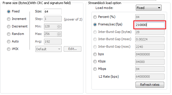
<1> Broadcast traffic test result.
- The log of the switch.
[3] 08:04:53 2017-10-12
"STP port state: MSTID 0, Eth 1/1 becomes non-forwarding."
level : 6, module : 5, function : 1, and event no. : 1
[2] 08:04:52 2017-10-12
"Unit 1, Port 1 link-down notification, reason: Auto Traffic Control - Broadcast."
level : 6, module : 5, function : 1, and event no. : 1
[1] 08:04:52 2017-10-12
"ATC broadcast traffic_control gets enabled on port 1."
level : 6, module : 5, function : 1, and event no. : 1
[0] 08:04:47 2017-10-12
"ATC broadcast storm alarm on port 1"
level : 6, module : 5, function : 1, and event no. : 1
- We can see the “Link Down Reason”, the port 1 has shutdown by broadcast ATC.
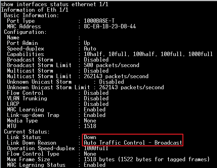
- Switch will send the trap to the syslog server.
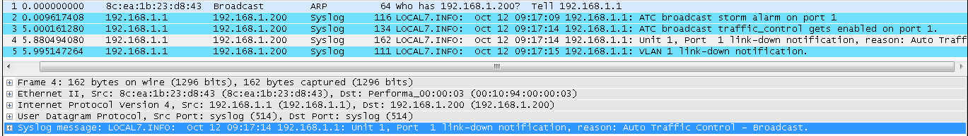
<2> Multicast traffic test result.
- The log of the switch.
[3] 09:19:53 2017-10-12
"VLAN 1 link-down notification."
level : 6, module : 5, function : 1, and event no. : 1
[2] 09:19:52 2017-10-12
"Unit 1, Port 1 link-down notification, reason: Auto Traffic Control - Multicast."
level : 6, module : 5, function : 1, and event no. : 1
[1] 09:19:52 2017-10-12
"ATC multicast traffic_control gets enabled on port 1."
level : 6, module : 5, function : 1, and event no. : 1
[0] 09:19:47 2017-10-12
"ATC multicast storm alarm on port 1"
level : 6, module : 5, function : 1, and event no. : 1
- We can see the “Link Down Reason”, the port 1 has shutdown by multicast ATC.
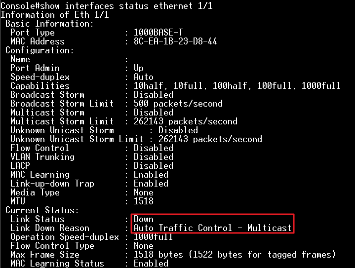
3. Switch will send the trap to the syslog server.
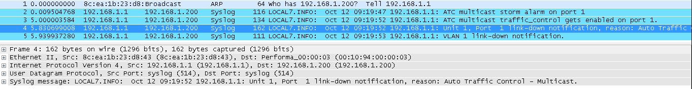
VLAN configuration support in standard MIB (Q-BRIDGE-MIB).
Support Model:
ECS4620 Series, ECS4510 Series, ECS4120 Series,
ECS4100 Series, ECS4110 Series, ECS4210 Series,
ECS3510-28T/52T, ES3528MV2, ES3510MA,
ECS2100 Series, ECS2110 Series
a. Create/Delete VLAN in vlan database.
SNMPSET command format:
snmpset -c private -v 2c <switch ip> < dot1qVlanStaticRowStatus | dot1qVlanStaticName >.< dot1qVlanIndex > < INTEGER | STRING > <value>
===Note===
dot1qVlanStaticRowStatus = active(1), notInService(2), notReady(3), createAndGo(4), createAndWait(5), destroy(6)
<Example 1>
Create VLAN10-Data, VLAN20-Multicast, and VLAN30-Other in vlan database.
(1) dot1qVlanStaticRowStatus (Integer 5 : createAndWait)
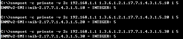
(2) dot1qVlanStaticRowStatus (Integer 1 : active)
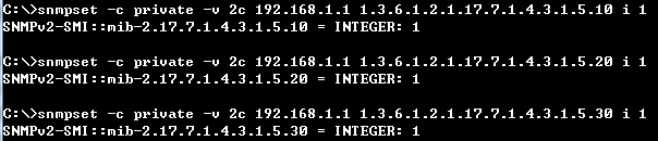
(3) dot1qVlanStaticName (String VLAN10:Data, VLAN20:Multicast, and VLAN30:Other)
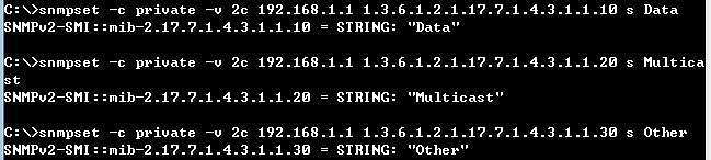
Check the result from SNMP and CLI.
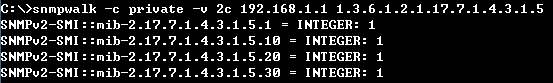
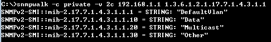
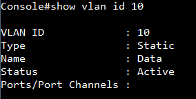
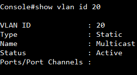
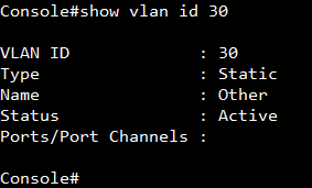
<Example 2>
Delete VLAN30-Other in vlan database.
(1) dot1qVlanStaticRowStatus (Integer 6 : destroy)

Check the result from SNMP and CLI.
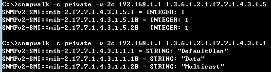
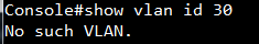
b. Add VLAN as member on port interface.
SNMPSET command format:
snmpset -c private -v 2c <switch ip> < dot1qVlanStaticEgressPorts | dot1qVlanStaticUntaggedPorts >.< dot1qVlanIndex > < HEX STRING > < PortList >
===Note===
PortList (Base syntax: OCTET STRING)
dot1qVlanStaticEgressPorts = 1 means port was assigned to the egress list for the VLAN; 0 means port was removed to the egress list for the VLAN.
dot1qVlanStaticUntaggedPorts = 1 means port transmits egress packets for the VLAN as untagged; 0 means port transmits egress packets for the VLAN as tagged.
<Example>
Configure VLAN setting on port interfaces as below.
Port1: PVID=10, VID=10(u)
Port2: PVID=1, VID=1(u), 20(t)
Port3: PVID=1, VID=1(t), 10(t), 20(t)
(1) dot1qVlanStaticEgressPorts (HEX STRING : VLAN1-7FFFFFF0, VLAN10-A0000000, VLAN20-60000000)
For VLAN10:
| Port ID | 1/1 | 1/2 | 1/3 | 1/4 | 1/5 | 1/6 | 1/7 | 1/8 | 1/9 | 1/10 | 1/x | 1/27 | 1/28 |
| Binary | 1 | 0 | 1 | 0 | 0 | 0 | 0 | 0 | 0 | 0 | 0 | 0 | 0 |
| Hex | A | 0 | 00000 | ||||||||||
| Port ID | 1/1 | 1/2 | 1/3 | 1/4 | 1/5 | 1/6 | 1/7 | 1/8 | 1/9 | 1/10 | 1/x | 1/27 | 1/28 |
| Binary | 0 | 1 | 1 | 0 | 0 | 0 | 0 | 0 | 0 | 0 | 0 | 0 | 0 |
| Hex | 6 | 0 | 00000 | ||||||||||
| Port ID | 1/1 | 1/2 | 1/3 | 1/4 | 1/5 | 1/6 | 1/7 | 1/8 | 1/9 | 1/10 | 1/x | 1/27 | 1/28 |
| Binary | 0 | 1 | 1 | 1 | 1 | 1 | 1 | 1 | 1 | 1 | 1 | 1 | 1 |
| Hex | 7 | F | FFFFF | ||||||||||
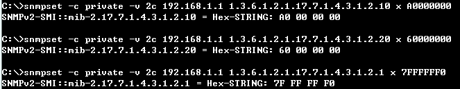
Check the result from SNMP and CLI.
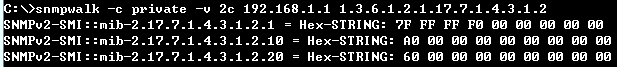
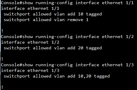
(2) dot1qVlanStaticUntaggedPorts (HEX STRING : VLAN1-5FFFFFF0, VLAN10-80000000, VLAN20-00000000)
For VLAN1:
| Port ID | 1/1 | 1/2 | 1/3 | 1/4 | 1/5 | 1/6 | 1/7 | 1/8 | 1/9 | 1/10 | 1/x | 1/27 | 1/28 |
| Binary | 0 | 1 | 0 | 1 | 1 | 1 | 1 | 1 | 1 | 1 | 1 | 1 | 1 |
| Hex | 5 | F | FFFFF | ||||||||||
| Port ID | 1/1 | 1/2 | 1/3 | 1/4 | 1/5 | 1/6 | 1/7 | 1/8 | 1/9 | 1/10 | 1/x | 1/27 | 1/28 |
| Binary | 1 | 0 | 0 | 0 | 0 | 0 | 0 | 0 | 0 | 0 | 0 | 0 | 0 |
| Hex | 8 | 0 | 00000 | ||||||||||
| Port ID | 1/1 | 1/2 | 1/3 | 1/4 | 1/5 | 1/6 | 1/7 | 1/8 | 1/9 | 1/10 | 1/x | 1/27 | 1/28 |
| Binary | 0 | 0 | 0 | 0 | 0 | 0 | 0 | 0 | 0 | 0 | 0 | 0 | 0 |
| Hex | 0 | 0 | 00000 | ||||||||||
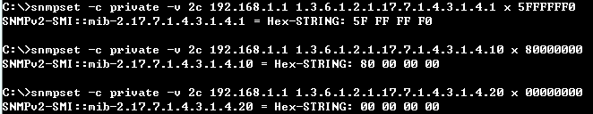
Check the result from SNMP and CLI.
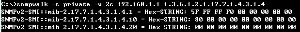
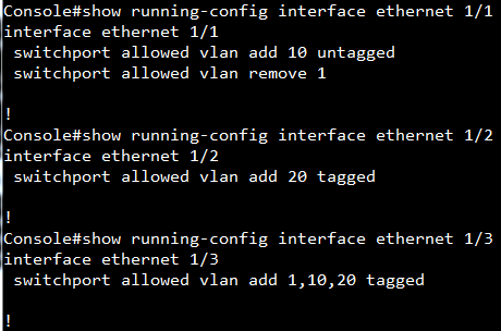
c. Configure PVID on port interface.
SNMPSET command format:
snmpset -c private -v 2c <switch ip> < dot1qPvid >.< PortIndex > < unsigned INTEGER > < VlanIndex>
<Example>
Configure VLAN setting on port interfaces as below.
Port1: PVID=10, VID=10(u)
Port2: PVID=1, VID=1(u), 20(t)
Port3: PVID=1, VID=1(t), 10(t), 20(t)
(1) dot1qPvid (unsigned INTEGER : port1-VLAN10, port2-VLAN1, port3-VLAN1)
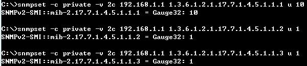
Check the result from SNMP and CLI.
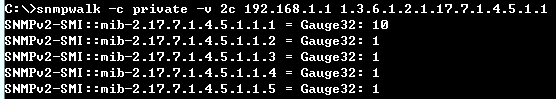
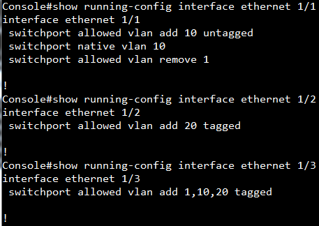
Models: ECS4620 series, ECS4510 series, ECS4120 series, ECS4110 series, ECS4100 series, ECS2100 series, ES3510MA
Introduction:
There are many AVP defined in TACACS+ draft show as below link,
https://tools.ietf.org/html/draft-grant-tacacs-02
Edgecore switch support only 3 AVP of them for TACACS+ authorization now:
1. service
2. shell
3. priv-lvl
About un-supported AVB, Edgecore switches consider the authorization to have failed.
Please refer to page No. 27 in the draft.
arg
An attribute-value pair that describes the command to be performed.
(see below)
The authorization arguments in both the REQUEST and the RESPONSE are
attribute-value pairs. The attribute and the value are in a single
ascii string and are separated by either a "=" (0X3D) or a "*"
(0X2A). The equals sign indicates a mandatory argument. The asterisk
indicates an optional one.
Optional arguments are ones that may be disregarded by either client
or daemon. Mandatory arguments require that the receiving side under-
stands the attribute and will act on it. If the client receives a
mandatory argument that it cannot oblige or does not understand, it
MUST consider the authorization to have failed. It is legal to send
an attribute-value pair with a NULL (zero length) value.
Attribute-value strings are not NULL terminated, rather their length
value indicates their end. The maximum length of an attribute-value
string is 255 characters. The following attributes are defined:
Problem: Users may not obtain correct privilege level if they receive mandatory un-supported AVP from TACACS server.
Solution: Change mandatory AVP to optional AVP on TACACS server.
TACACS setting as shown below:
There are two users.
User test1 with mandatory AVP “idletime”.
User test2 with optional AVP “idletime”.
/etc/tacacs+/tac_plus.conf
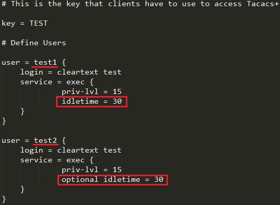
User test1 obtain privilege 0.
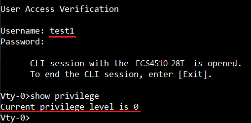
User test2 obtain privilege level 15.
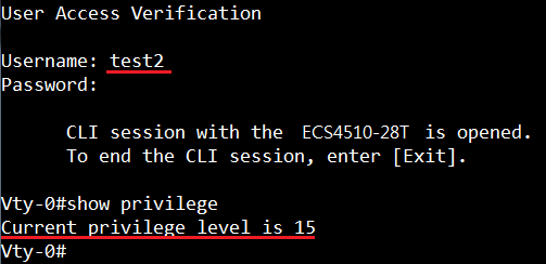
(Example by ECS2100)
Introduction:
Remote Switched Port Analyzer (RSPAN) allows you to mirror traffic from remote switches for analysis on a local destination port.
In the following example, you can use PC1 to capture packets between PC2 and switch C port #4.
Topology:
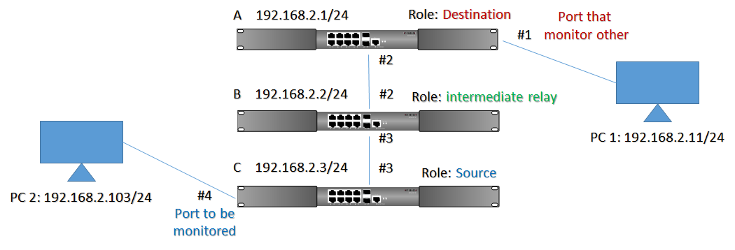
Configuration:
Switch A
1. Configure A RSPAN VLAN (here is VLAN 2 since VLAN 1 cannot be the RSPAN VLAN)
A#configure
A(config)#vlan database
A(config-vlan)#vlan 2 media ethernet rspan
2. Configure the destination port (here is #1) for session 1
A(config)#rspan session 1 destination interface ethernet 1/1
3. Configure the switch role & uplink port
A(config)#rspan session 1 remote vlan 2 destination uplink ethernet 1/2
4. Check by show RSPANA#show rspan session 1
A#show rspan session 1
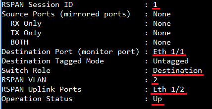
Switch B
1. Configure A RSPAN VLAN
B(config)#vlan database
B(config-vlan)#vlan 2 media ethernet rspan
2. Configure the switch role & uplink port
B(config)#rspan session 1 remote vlan 2 intermediate uplink ethernet 1/2
B(config)#rspan session 1 remote vlan 2 intermediate uplink ethernet 1/3
3. Check by show RSPAN
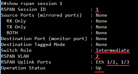
Switch C
1. Configure A RSPAN VLAN
C(config)#vlan database
C(config-vlan)#vlan 2 media ethernet rspan
2. Configure the destination port (here is #4) for session 1
C(config)#rspan session 1 source interface ethernet 1/4
3. Configure the switch role & uplink port
C(config)#rspan session 1 remote vlan 2 source uplink ethernet 1/3
4. Check by show RSPAN
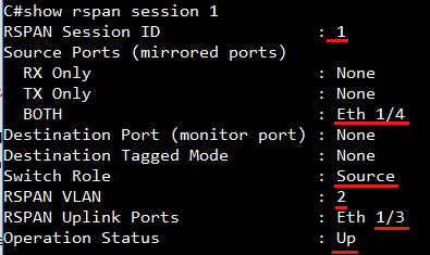
PC 2 ping switch C, and Pc1 will receive packets
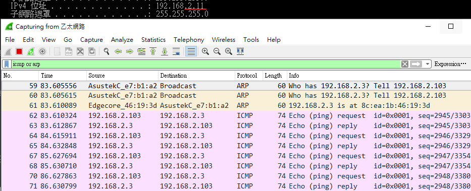
Scenario: Apply VLAN translation on port 1 of ECS4620-28P.
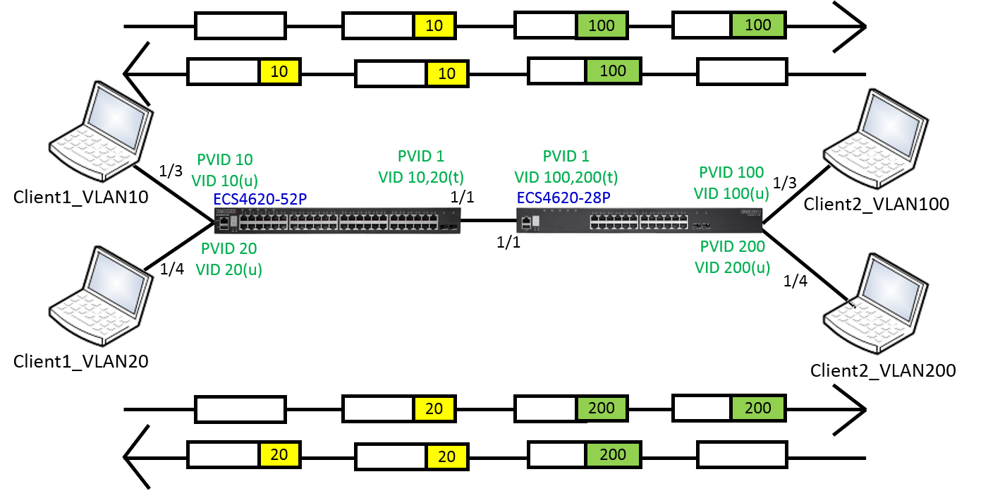
Configuration on ECS4620-52P:
ECS4620-52P#con
ECS4620-52P(config)#vlan database
ECS4620-52P(config-vlan)#vlan 10,20
ECS4620-52P(config-vlan)#ex
ECS4620-52P(config)#interface ethernet 1/1
ECS4620-52P(config-if)#switchport allowed vlan add 10,20 tagged
ECS4620-52P(config-if)#ex
ECS4620-52P(config)#interface ethernet 1/3
ECS4620-52P(config-if)#switchport allowed vlan add 10 untagged
ECS4620-52P(config-if)#switchport native vlan 10
ECS4620-52P(config-if)#switchport allowed vlan remove 1
ECS4620-52P(config-if)#ex
ECS4620-52P(config)#interface ethernet 1/4
ECS4620-52P(config-if)#switchport allowed vlan add 20 untagged
ECS4620-52P(config-if)#switchport native vlan 20
ECS4620-52P(config-if)#switchport allowed vlan remove 1
ECS4620-52P(config-if)#end
ECS4620-52P#
Configuration on ECS4620-28P:
ECS4620-28P#con
ECS4620-28P(config)#vlan database
ECS4620-28P(config-vlan)#vlan 100,200
ECS4620-28P(config-vlan)#ex
ECS4620-28P(config)#interface ethernet 1/3
ECS4620-28P(config-if)#switchport allowed vlan add 100 untagged
ECS4620-28P(config-if)#switchport native vlan 100
ECS4620-28P(config-if)#switchport allowed vlan remove 1
ECS4620-28P(config-if)#ex
ECS4620-28P(config)#interface ethernet 1/4
ECS4620-28P(config-if)#switchport allowed vlan add 200 untagged
ECS4620-28P(config-if)#switchport native vlan 200
ECS4620-28P(config-if)#switchport allowed vlan remove 1
ECS4620-28P(config-if)#ex
ECS4620-28P(config)#interface ethernet 1/1
ECS4620-28P(config-if)#switchport allowed vlan add 100,200 tagged
ECS4620-28P(config-if)#switchport vlan-translation 10 100
ECS4620-28P(config-if)#switchport vlan-translation 20 200
ECS4620-28P(config-if)#end
[CLI Command] switchport vlan-translation original-vlan new-vlan
Port1 of ECS4620-28P
Console(config-if)#switchport vlan-translation 10 100
Ingress -> map original-vlan(VLAN10) to new-vlan(VLAN100)
Egress -> map new-vlan(VLAN100) to original-vlan(VLAN10)
[SNMPSET command format]
snmpset -v 2c -c private {switch ip} { vlanTraslationPortStatus | vlanTraslationPortNewVid }.{vlanTraslationPortIndex}.{vlanTraslationPortOldVid} {integer} {value}
For vlanTraslationPortStatus, OID 1.3.6.1.4.1.259.10.1.41.1.12.22.1.4
Set OID 1.3.6.1.4.1.259.10.1.41.1.12.22.1.4 to valid(1) to create an entry.
Set OID 1.3.6.1.4.1.259.10.1.41.1.12.22.1.4 to invalid(2) to destroy an entry.
For vlanTraslationPortNewVid, OID 1.3.6.1.4.1.259.10.1.41.1.12.22.1.3
Specify the new VLAN ID that will be mapped to.
For vlanTraslationPortIndex: The port interface of vlanTraslationPortIndex
The interface identified by a particular value of this index is the same interface as identified by the same value of ifIndex in the IF-MIB.
For vlanTraslationPortOldVid,
Specify the original VLAN ID that the traffic arrive.
(1) vlanTraslationPortStatus, OID 1.3.6.1.4.1.259.10.1.41.1.12.22.1.4 ; vlanTraslationPortIndex = 1 ; vlanTraslationPortOldVid = 10 (Integer 1 :valid)

vlanTraslationPortStatus, OID 1.3.6.1.4.1.259.10.1.41.1.12.22.1.4 ; vlanTraslationPortIndex = 1 ; vlanTraslationPortOldVid = 20 (Integer 1 :valid)

(2) vlanTraslationPortNewVid, OID 1.3.6.1.4.1.259.10.1.41.1.12.22.1.3 ; vlanTraslationPortIndex = 1 ; vlanTraslationPortOldVid = 10 (Integer 100 :new vlan ID vlan100)

vlanTraslationPortNewVid, OID 1.3.6.1.4.1.259.10.1.41.1.12.22.1.3 ; vlanTraslationPortIndex = 1 ; vlanTraslationPortOldVid = 20 (Integer 200 :new vlan ID vlan200)

Display the configuration settings for VLAN translation.
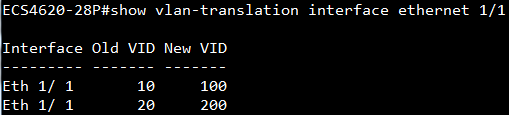
Result
VLAN10 - Client1(192.168.10.88) and VLAN100 - Client2(192.168.10.99) can ping each other.
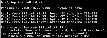
MAC-address-table of ECS4620-52P
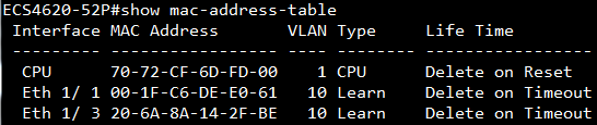
MAC-address-table of ECS4620-28P
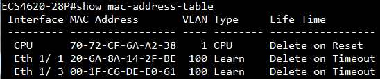
VLAN20 - Client1(192.168.20.88) and VLAN200 - Client2(192.168.20.99) can ping each other.
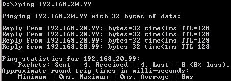
MAC-address-table of ECS4620-52P
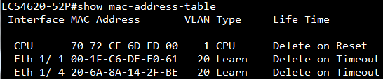
MAC-address-table of ECS4620-28P
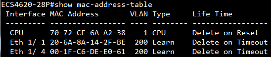
Scenario:
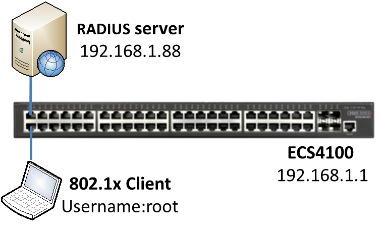
In this example, we will use “FreeRADIUS” as accounting server.
Procedures:
- Configure the RADIUS server parameters and switch's IP address.
Tips: the “encryption key” is defined by user on RADIUS server, thus it must be configured correctly.
Console#configure
Console(config)#interface vlan 1
Console(config-if)#ip address 192.168.1.1/24
Console(config-if)#exit
Console(config)#radius-server 1 host 192.168.1.88 key support
- Enable the dot1x on global mode.
Console(config)#dot1x system-auth-control
- Enable dot1x and accounting function on the port interface, and let the client connect to this port.
Console(config)#aaa accounting dot1x default start-stop group radius
Console(config)#interface ethernet 1/2
Console(config-if)#dot1x port-control auto
Console(config-if)#accounting dot1x default
After the client gets authentication successfully, then switch starts to send the accounting packet (Figure 1) to the FreeRADIUS server.
Figure 1: Capture the accounting packet on FreeRADIUS server.
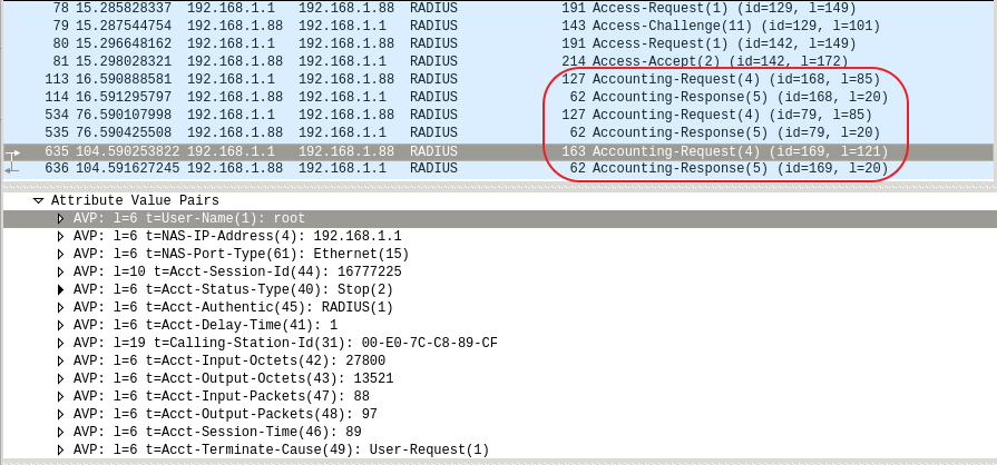
When the client's connection is disconnected, switch will send the total traffic information of this client.
Figure 2: The traffic information of accounting log in the FreeRADIUS server.
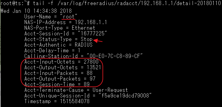
Tips: If the FreeRADIUS receive the accounting packet, it start to record the log automatically by default. You can find the log in this path “/var/log/freeradius/radacct/”
Supported models:
ECS4620 series, ECS4510 series, ECS4120 series, ECS4100 series, ECS3500 series, ECS4110 series, ECS2110 series, ECS2100 series
On Edgecore switches, non-STP loopback detection is another function to prevent the loop issue and it can detect the loop for each VLAN.
- Configuration example:
Console(config)#loopback-detection
Console(config)#interface ethernet 1/1
Console(config-if)#switchport allowed vlan add 1-10 tagged
Console(config-if)#loopback-detection
Then port 1 will send 10 LBD packets to detect the loop for each VLAN.
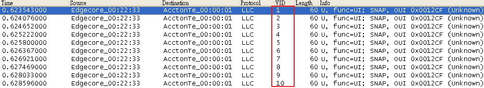
*Notice: Since loopback-detection will detect the loop for each VLAN, the, "ingress-filtering" function will be enabled automatically when you enable loopback-detection on an interface.
If switch receives its own LBD packet then it will know that a loop occurred on this port and VLAN. The user could know that the port was shutdown by LBD from "LBD status", "Interface status" and "Log".
LBD status:
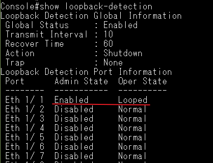
Interface status:
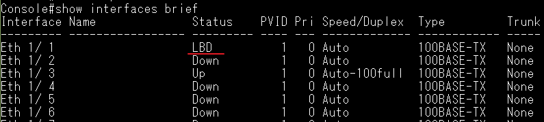
Log:
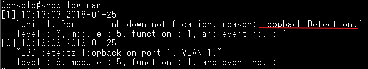
- The user can manually configure the following loopback-detection parameters:
Transmit Interval
The user can specify the interval time for transmitting LBD packets. By default, it is 10s.
Console(config)#loopback-detection transmit-interval ?
<1-32767> Specifies transmission interval in seconds
Recover Time
The user can specify “recover time” when the port is shutdown by LBD, by default it is 60s.
Console(config)#loopback-detection recover-time ?
0 Disables auto recovery
<60-1000000> Specifies recovery time in seconds
After the time is up then the port’s link will be recovered (if the network is no longer looped), and the switch will have a log.
[11] 10:14:03 2018-01-25
"LBD recovers port 1."
level : 6, module : 5, function : 1, and event no. : 1
Action
There are three actions for loopback-detection, by default it is “shutdown”.
Console(config)#loopback-detection action ?
block Specifies action to block looped VLANs from the interface
none Specifies action to do nothing
shutdown Specifies action to shutdown the interface
The status on each actions when switch detect the loop:
| show loopback-detection | show interfaces brief | show log ram | |
| Block | Looped (The traffic will be blocked.) |
Link is UP | LBD detects loopback on port XX, VLAN XX |
| None | Looped (The traffic still will be forwarded.) |
Link is UP | LBD detects loopback on port XX, VLAN XX |
| Shutdown | Looped | Link is DOWN | 1. LBD detects loopback on port XX, VLAN XX. 2. reason: Loopback Detection |
SNMP Trap
User can specify the switch to send a SNMP trap when it detect a loop.
Console(config)#loopback-detection trap ?
both Specifies to send both detection and recovery traps
detect Specifies to send trap when loop is detected
none Specifies to not send any trap
recover Specifies to send trap when recovery is done
- STP LBD and non-STP LBD default setting on each models:
| STP loopback detection | non-STP loopback detection | Ingress filtering | |
| ECS4620 series | Enable | Disable | Disable |
| ECS4510 series | Enable | Disable | Disable |
| ECS4120 series | Enable | Disable | Disable |
| ECS4100 series | Disable | Enable | Enable |
| ECS4110 series | Enable | Disable | Disable |
| ECS2110 series | Disable | Enable | Enable |
| ECS2100 series | Disable | Enable | Enable |
In a practical application, we will connect two different ISPs to achieve router redundancy; the Topology will show as follow:
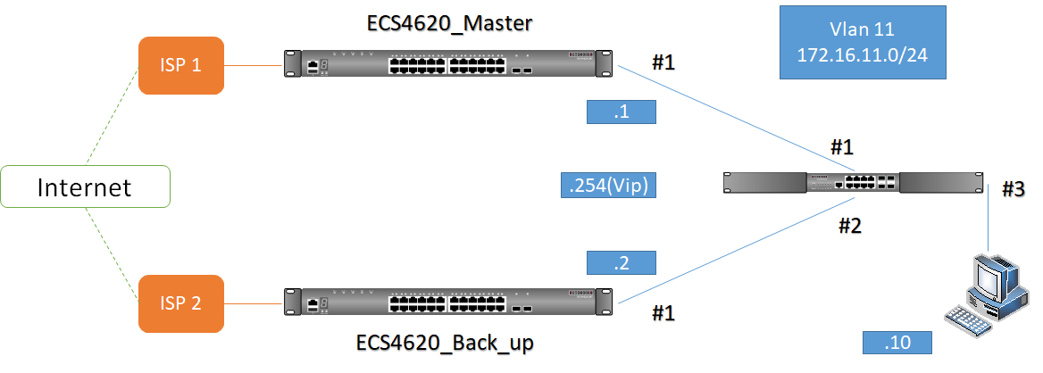
Since there is no loop when ECS4620 connects to the ISP, there’s no need to disable the spanning-tree feature, and no need to connect a link between Master & Back-up switches, or set default route to each other. Instead, Master and Back up switches need to add a default route to their ISP.
VRRP Recover and Status
- default
As normal situation, show vrrp brief as follow:
Master:
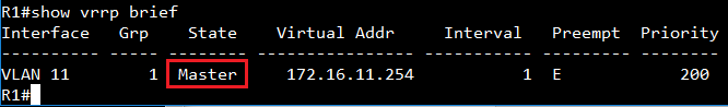
Back up:

If Master switch’s port #1 link-down, Master switch’s state will change to “Initial”.
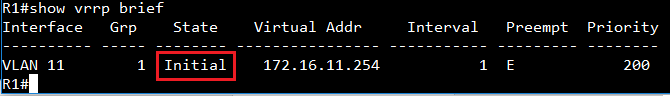
At same time, Back up switch’s state will change to “Master”
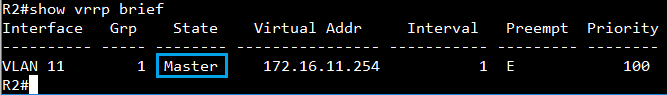
Then, when Master switch’s port #1 recovers, Master switch will preempt the Master state back.
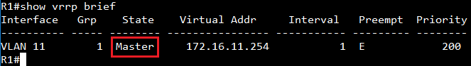
At same time, Back up switch’s state will back to “Backup”
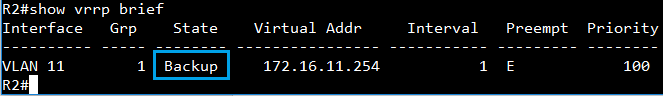
- No preempt
If you don’t want Master Switch to preempt back, you can use following commands:
R1(config)#interface vlan 11
R1(config-if)#no vrrp 1 preempt
Switch’s Preempt status will change to “D” (Disabled).
In this situation, even Master switch’s port #1 recover,

Master switch still not preempt the “Master” state back
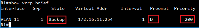
- Preempt with delay time
R1(config)#interface vlan 11
R1(config-if)#vrrp 1 preempt delay 30
You can assign delay time in <0-120> seconds, default is 0s.
In my example (30s), when Master switch port #1 recover within 30s, Master still in “Backup” state.
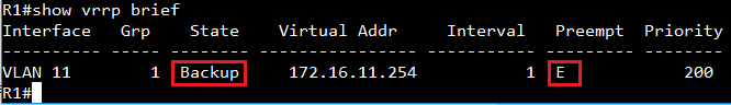
After connect 30s, Master switch preempt the “Master” state back.
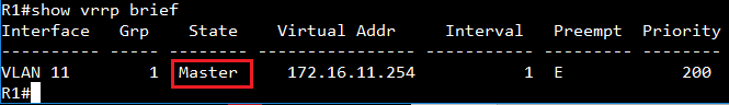
Example: (Test on ES3510MA)
Exception: allow port 1 to learn only the MAC addresses specified in the mac-filter.
Topology:
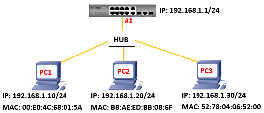
Here's the configuration:
Setting “network-access mac-filter”
Console(config)#network-access mac-filter 2 mac-address 00-E0-4C-68-01-5A
Console(config)#network-access mac-filter 2 mac-address B8-AE-ED-BB-08-6F
Console(config)#interface ethernet 1/1
Console(config-if)#port security "enable port security"
Console(config-if)#port security max-mac-count 3 "allow port 1 could learn three MAC-Address"
Console(config-if)#network-access port-mac-filter 2 "MAC-Address-Table only learn MAC-Address which I setting."
Result:
Check MAC-address-table.
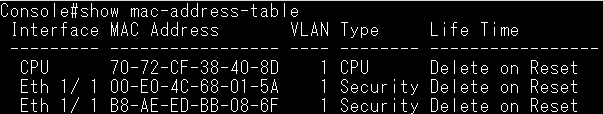
Check port security.
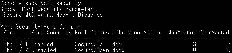
Ping from switch to PC1, PC2, PC3.
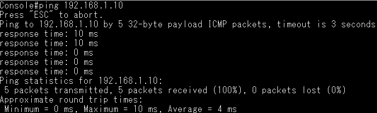
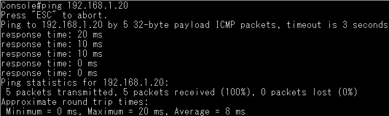
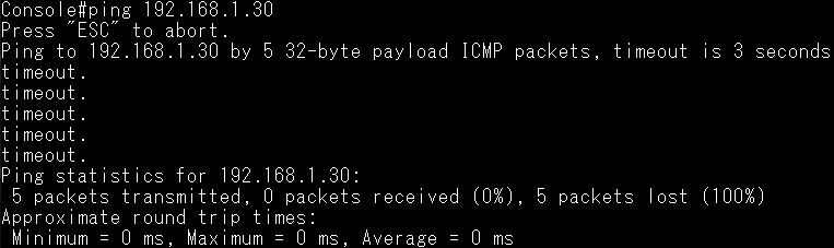
Capture the packet from PC3.
PC3 could receive ARP Request packet from switch, and reply ARP Reply to switch.
Since I set the mac-filter on the switch, that's why switch didn't learn the PC3's MAC, and ping failed.
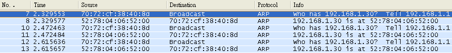
When a group's timer expires then it will be removed from IGMPSNP group table /MVR member table, therefore, this group's multicast traffic will stop forwarding. Once the switch received the group's IGMP report packet, then the timer will start to calculate or renew.
IGMP snooping:
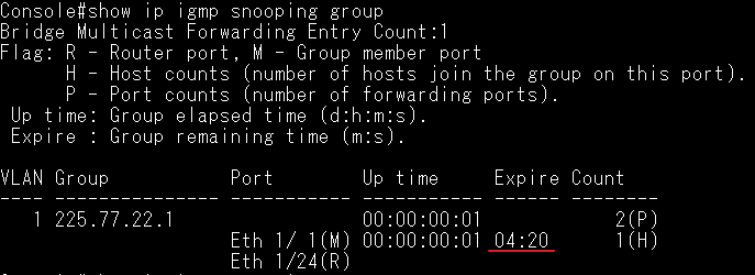
IGMPSNP Expire time =
Last Member Query Count x Query Interval + Query Response Interval
For Example:
Default: 125 x 2 + 10 = 260 seconds = 4 minutes and 20 seconds
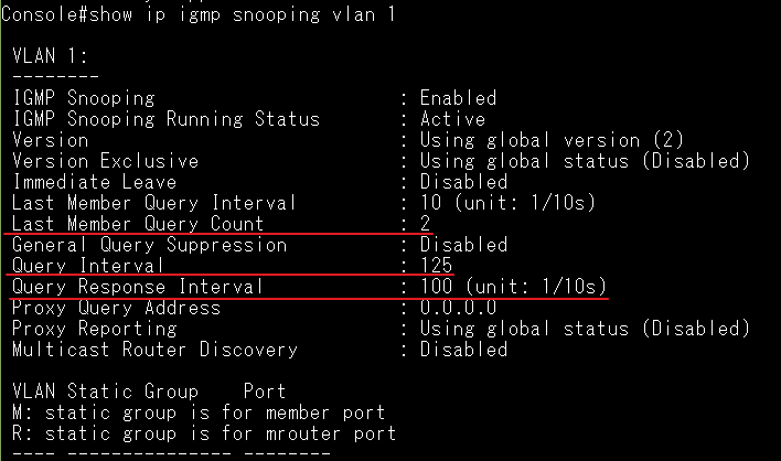
MVR:
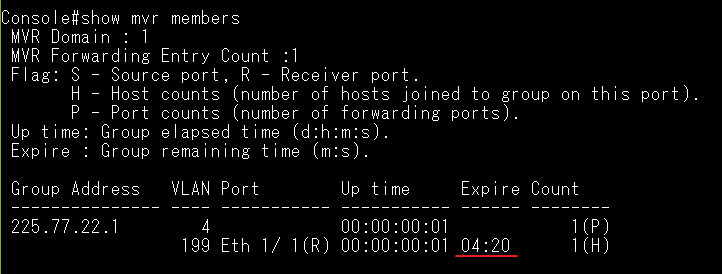
MVR Expire time =
MVR Robustness Value x MVR Proxy Query Interval + 10 seconds (static)
For Example:
Default: 125 x 2 + 10 = 260 seconds = 4 minutes and 20 seconds
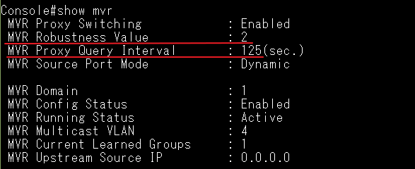
Notice: Enable/Disable “MVR Proxy Switching” will not affect to the expire time.
When the switch boots with a factory default configuration, it supports automatically obtain IP address and configuration file from remote server. Once the switch installs the new configuration, it could automatically upgrade the current operational code when a new version is detected on the server.
Topology:

Procedure:
Step 1:
Prepare a DHCP Server and TFTP Server, and connect it to the ECS4100-12T.
Step 2:
Prepare ECS4100-12T’s configuration and the newer firmware.
ECS4100-12T’s configuration:
Enable Automatic Code Upgrade function, and configure the IP address or other needed functions.
Console(config)#upgrade opcode auto
Console(config)#upgrade opcode reload
Console(config)#upgrade opcode path tftp://192.168.1.2/
Console(config)#interface vlan 1
Console(config-if)#ip address 192.168.1.1/24
Step 3:
Save the configuration(Copy running-config) to remote device for more modification, then put the used configuration to the Server.
Console#copy running-config tftp
TFTP server IP address: 192.168.1.2
Destination file name: test.cfg
Success.
Console#
Step 4:
Modify the firmware name to “ECS4100-series.bix”.
Please note that the name for the new image stored on the TFTP server must be ECS4100-series.bix.

Step 5:
Configure the setting on DHCP Server.
Must be enabled option 66/67 on DHCP Server.
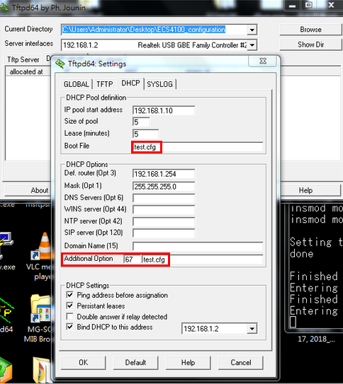
Step 6:
Boot ECS4100-12T with factory default configuration.
Console# configure
Console(config)# boot system config:Factory_Default_config.cfg
Console(config)# exit
Console# reload
Step 7:
Enable DHCP Dynamic Provision.
Console(config)#ip dhcp dynamic-provision
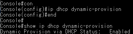
Step 8:
ECS4100-12T get the IP address from DHCP Server.
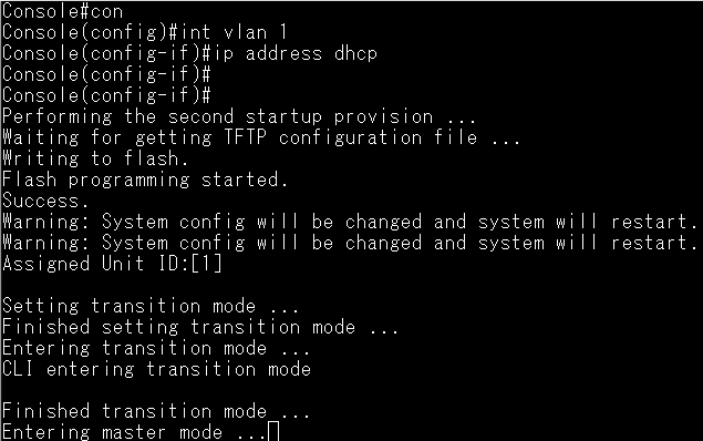
Capture the DHCP packets which include option66/67.
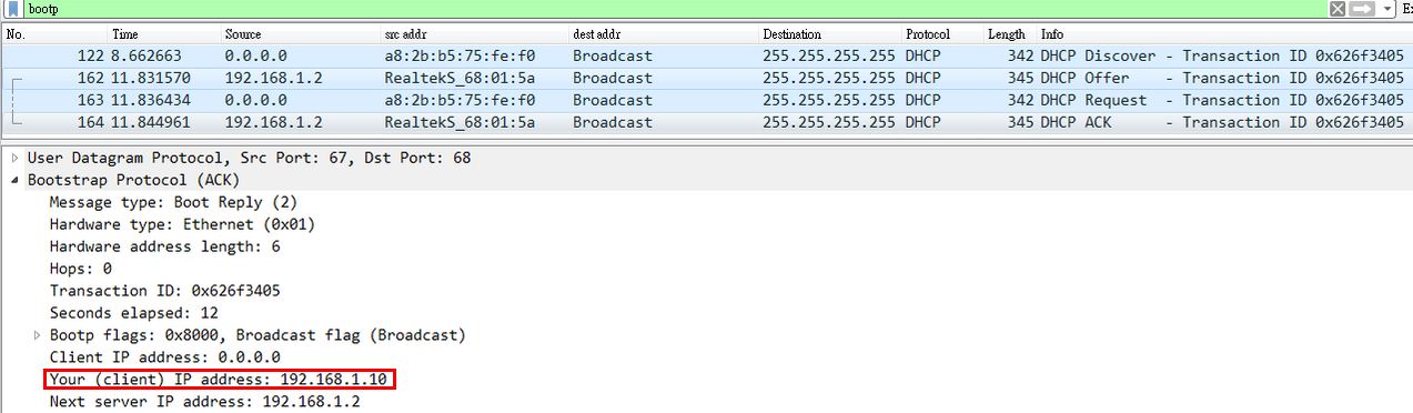
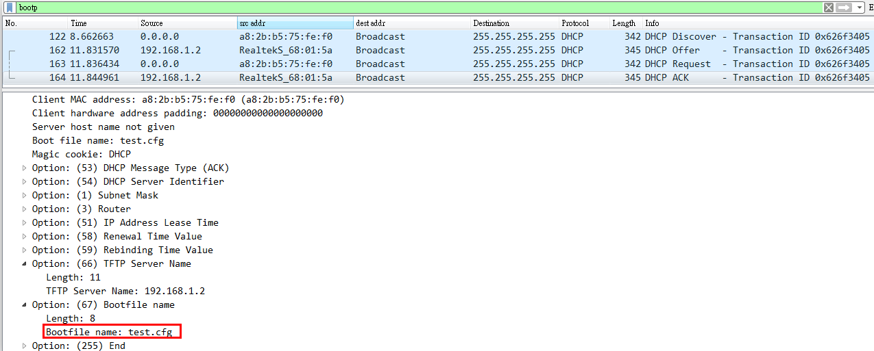
After ECS4100-12T installs the new configuration, it starts to look for a new image.
Then ECS4100-12T automatically upgrades the current operational code when a new version is detected on the server.
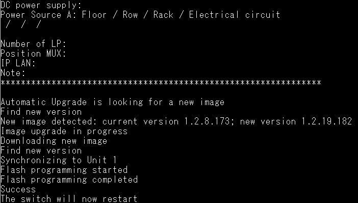
Support models:
ES3510MA, ES3528MV2, ECS3510-28T/52T, ECS4110 series, ECS4510 series, ECS4620 series
Scenario:
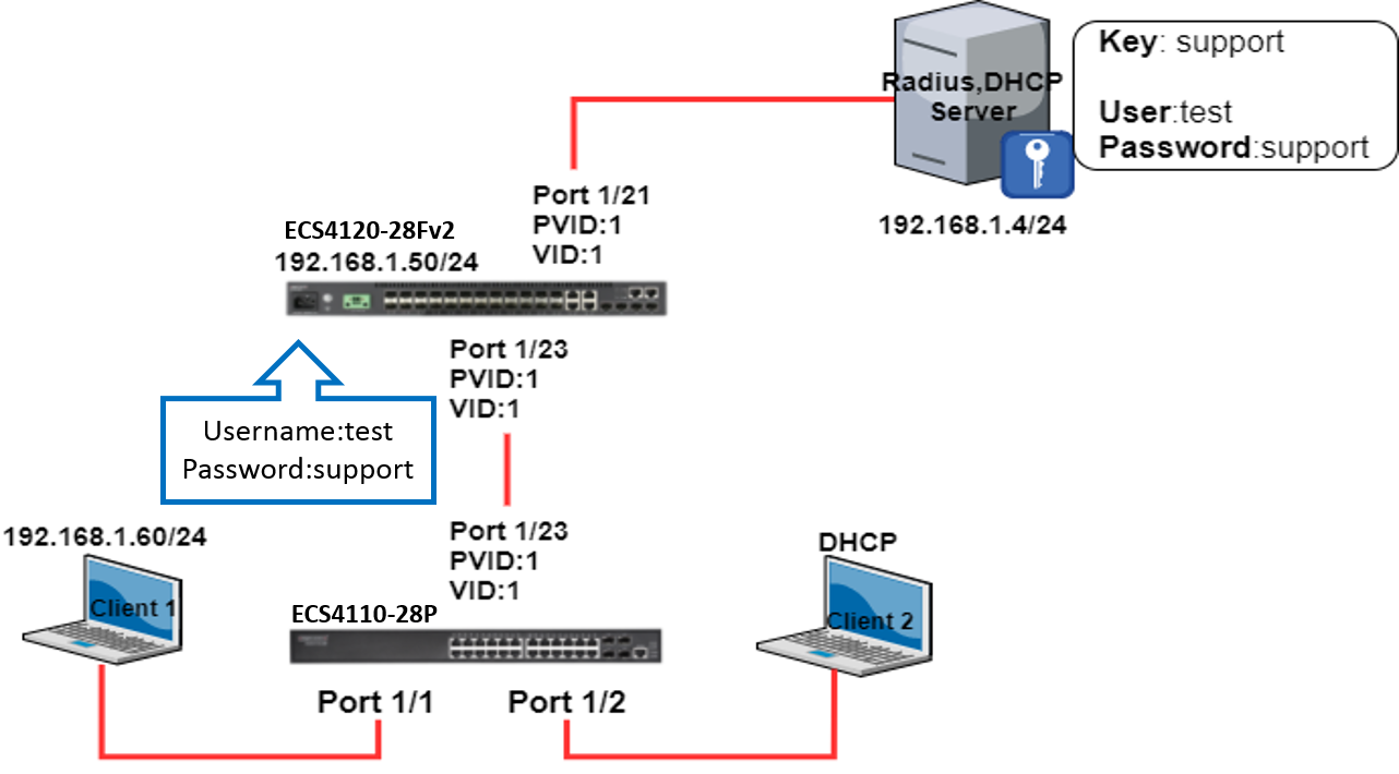
Test procedures:
Step 1) Configure the management IP address
ECS4120-28Fv2:
ECS412028Fv2#configure
ECS412028Fv2(config)#interface vlan 1
ECS412028Fv2(config-if)#ip address 192.168.1.50/24
Step 2) Define an external RADIUS server
ECS4120-28Fv2:
ECS412028Fv2#configure
ECS412028Fv2(config)#radius-server 1 host 192.168.1.4 key support
Step 3) Check the configuration of RADIUS
ECS412028Fv2#show radius-server
Remote RADIUS Server Configuration:
Server 1:
Server IP Address: 192.168.1.4
Authentication Port Number : 1812
Accounting Port Number : 1813
Retransmit Times : 2
Request Timeout : 5
Step 4) Enable 802.1x port authentication globally on ECS4120-28Fv2
ECS4120-28Fv2:
ECS412028Fv2#configure
ECS412028Fv2(config)#dot1x system-auth-control
Step 5) Configure 802.1x mode on switch port
ECS4120-28Fv2:
ECS412028Fv2#configure
ECS412028Fv2(config)#interface ethernet 1/23
ECS412028Fv2(config-if)#dot1x port-control auto
Step 6) Allow multiple hosts connect to the same switch port
ECS4120-28Fv2:
ECS412028Fv2#configure
ECS412028Fv2(config)#interface ethernet 1/23
ECS412028Fv2(config-if)#dot1x operation-mode multi-host
Step 7) Check the 802.1x configuration status is correct
ECS4120-28Fv2:
ECS412028Fv2#show dot1x
Global 802.1X Parameters:
System Auth Control : Enabled
Authenticator Parameters:
EAPOL Pass Through : Disabled
802.1X Port Summary
Port Type Operation Mode Control Mode Authorized
-------- ------------- -------------- ------------------ ---------
Eth 1/21 Disabled Single-Host Force-Authorized Yes
Eth 1/22 Disabled Single-Host Force-Authorized N/A
Eth 1/23 Authenticator Multi-Host Auto N/A
Eth 1/24 Disabled Single-Host Force-Authorized N/A
Eth 1/25 Disabled Single-Host Force-Authorized N/A
Eth 1/26 Disabled Single-Host Force-Authorized N/A
Step 8) Try to ping the radius server from Client1
Client 1 : Ping failed because the port was not authenticated by RADIUS server.
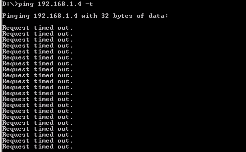
Step 9) Check the version on ECS4110-28P which support dot1x supplicant mode
ECS4110-28P(DUT):
Dut1#show version
Unit 1
Serial Number : EC1427000158
Hardware Version : R0A
EPLD Version : 0.00
Number of Ports : 28
Main Power Status : Up
Role : Master
Loader Version : 1.2.0.1
Linux Kernel Version : 2.6.22.18
Boot ROM Version : 0.0.0.1
Operation Code Version : 1.2.3.13
Step 10) Enable dot1x supplicant mode on port interface
ECS4110-28P(DUT):
Dut1#configure
Dut1(config)#interface ethernet 1/23
Dut1(config-if)#dot1x pae supplicant
Step 11) Set up the dot1x supplicant Username and Password
ECS4110-28P(DUT):
Dut1#configure
Dut1(config)#dot1x identity profile username test
Dut1(config)#dot1x identity profile password support
Step 12) Reconnect the port 1/23 of ECS4110-28P to re-authenticate.
ECS4110-28P(DUT):
Dut1#configure
Dut1(config)#interface ethernet 1/23
Dut1(config-if)#shutdown
Dut1(config-if)#no shutdown
Step 13) Check the status of dot1x on ECS4120-28Fv2
ECS4120-28Fv2:
ECS412028Fv2#show dot1x interface ethernet 1/23
802.1X Authenticator is enabled on port 1/23
Reauthentication : Disabled
Reauth Period : 3600 seconds
Quiet Period : 60 seconds
TX Period : 30 seconds
Supplicant Timeout : 30 seconds
Server Timeout : 10 seconds
Reauth Max Retries : 2
Max Request : 2
Operation Mode : Multi-Host
Port Control : Auto
Maximum MAC Count : 5
Intrusion Action : Block traffic
Supplicant : 70-72-CF-C8-58-8F // ECS4110-28P(DUT)’s MAC Address
Authenticator PAE State Machine
State : Authenticated
Reauth Count : 0
Current Identifier : 1
ECS4110-28P(DUT):
Dut1#show dot1x
Global 802.1X Parameters:
System Auth Control : Disabled
Authenticator Parameters:
EAPOL Pass Through : Disabled
Supplicant Parameters:
Identity Profile Username : test
802.1X Port Summary
Port Type Operation Mode Control Mode Authorized
-------- ------------- -------------- ------------------ ----------
Eth 1/22 Disabled Single-Host Force-Authorized N/A
Eth 1/23 Supplicant Single-Host Force-Authorized Yes
Eth 1/24 Disabled Single-Host Force-Authorized N/A
Eth 1/25 Disabled Single-Host Force-Authorized N/A
802.1X Port Details
802.1X Authenticator is disabled on port 1/23
802.1X Supplicant is enabled on port 1/23
Authenticated : Yes
Auth-period : 30 seconds
Held-period : 60 seconds
Start-period : 30 seconds
Max-start : 3
Step 14) Retrieve the packet by wireshark on RADIUS Server
Authentication Successfully
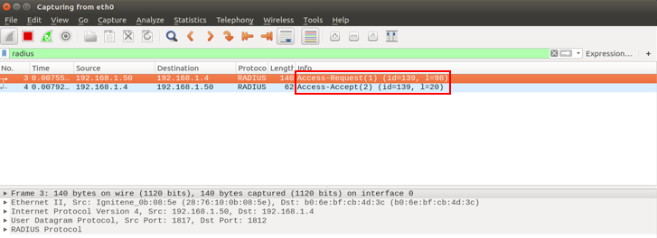
Step 15) Try to ping the radius server again from Client1
Client 1 : Ping Successfully
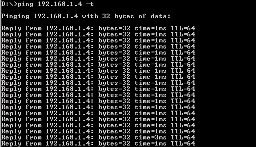
Client 2 : Successfully obtain the IP address by DHCP Server and ping to radius server
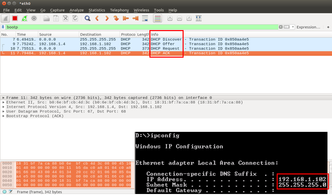
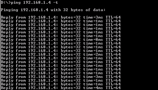
This article uses ECS4100-28T for the example.
Step 1:
Setting the static MAC address (40-16-7e-66-a4-36) on port 7.
snmpset -v 2c -c private 192.168.1.1 .1.3.6.1.2.1.17.7.1.3.1.1.3.1.64.22.126.102.164.53.0 x 02
64.22.126.102.164.53 = 40-16-7e-66-a4-36
Those value means the MAC address which you want to set and MAC address need be converted from Hexadecimal to Decimal.
| Hexadecimal | -> | Decimal |
| 40 | -> | 64 |
| 16 | -> | 22 |
| 7e | -> | 126 |
"02" means port 7. "x" means octets.
- Here's the way to calculate the value.
Please see this form to understand how to specify the value for port number.
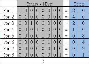
- If you want to set the port 1, then the value is 80.

Note:
You cannot use single digit, ex: "x 8" in the end, it will fail.
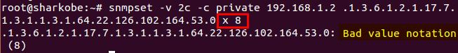
The correct value of port 1 should be double digits, ex: "x 80".
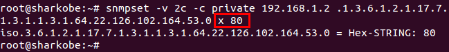
Here's another example.
- If you want to set the port 10, the value is 0040.
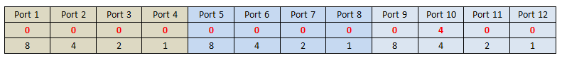
Step 2:
Setting the static MAC address type.
snmpset -v 2c -c private 192.168.1.1 .1.3.6.1.2.1.17.7.1.3.1.1.4.1.64.22.126.102.164.53.0 i 3
"i" means integer32.
"3" means type 3.
- There are five types for this value, Edgecore switch supported two types.
permanent(3)
deleteOnReset(4)

Here's the Result:
We can see the MAC address which be configured to MAC table via SNMP successfully.
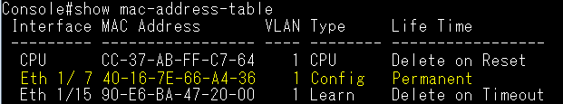
Overview
The Two-Way Active Measurement Protocol (TWAMP) is an open protocol for measuring network performance between any two devices supporting the TWAMP protocol.
TWAMP uses the methodology and architecture of OWAMP to define an open protocol for measurement of two-way or round-trip metrics, in addition to the one-way metrics of OWAMP.
TWAMP consists of the following two protocols as L3 layer monitor. When starting the performance measurement session (TWAMP-Control), use the TWAMP control protocol. It is layered over TCP and is used to initiate and set up test sessions. The TWAMP test protocol is layered over UDP and is used for sending and receiving the test packets for performance measurement (TWAMP-Test).
Operational Concept
TWAMP consists of a network architecture in which a combination of Control-Client and Session-Sender is a set of hosts; meanwhile, Server and Session-Reflector are configured on the other host. Our switch supports the function of Server and Session-Reflector (RFC5357).
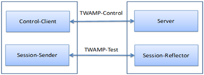
Establishment of Control Connection
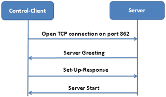
Establishment of Test Session
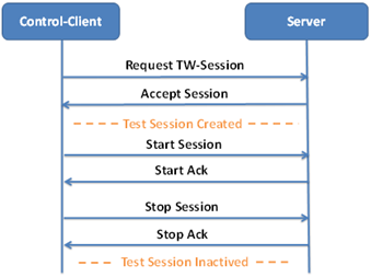
Configuration (Support CLI command only currently)
TWAMP Reflector is disabled by default.
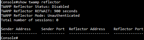
Enable TWAMP Reflector function.

Display current status and timer.
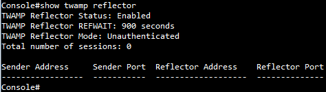
TWAMP Reflector REFWAIT timer:
Close the session that has been started when no packet associated with that session has been received for REFWAIT seconds.(Default: 900 seconds; configurable range is from 30 - 3600 seconds)
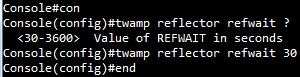
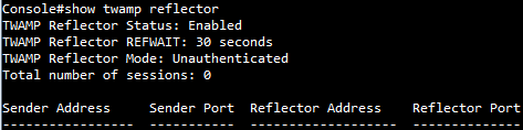
[Result]
1) TWAMP clients use IPv4 address to establish session and send test packets.
Display current status and session.
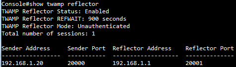
There is no packet loss via IPv4 address.
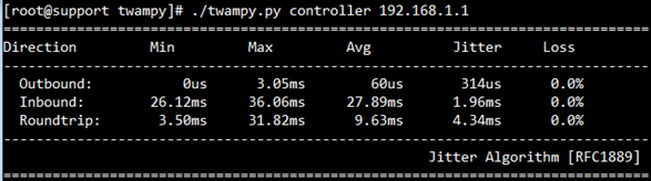
2) The maximum number of test sessions is 5.
TWAMP works correctly when the server and clients are in the same IPv4 network segments.
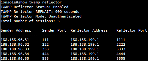
3) TWAMP works correctly when the server and clients are in the different IPv4 network segments.
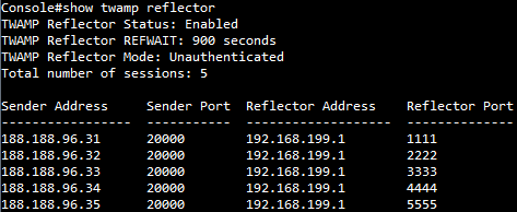
4) TWAMP works correctly when the server and clients are in the same IPv6 network segments.
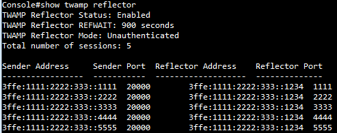
5) TWAMP works correctly when the server and clients are in the different IPv6 network segments.
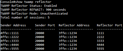
Support models and software version:
ECS4120 series v1.2.2.18 and above.
ECS4100 series v1.2.36.191 and above.
The following is the example for ECS4120 series.
C:\>snmpset -v 2c -c private 192.168.1.1 1.3.6.1.4.1.259.10.1.45.1.16.1.2.1.6.1 i 1
SNMPv2-SMI::enterprises.259.10.1.45.1.16.1.2.1.6.1 = INTEGER: 1
C:\>snmpset -v 2c -c private 192.168.1.1 1.3.6.1.4.1.259.10.1.45.1.16.1.2.1.10.1 i 100000
SNMPv2-SMI::enterprises.259.10.1.45.1.16.1.2.1.10.1 = INTEGER: 100000
C:\>snmpset -v 2c -c private 192.168.1.1 1.3.6.1.4.1.259.10.1.45.1.16.1.2.1.7.2 i 1
SNMPv2-SMI::enterprises.259.10.1.45.1.16.1.2.1.7.2 = INTEGER: 1
C:\>snmpset -v 2c -c private 192.168.1.1 1.3.6.1.4.1.259.10.1.45.1.16.1.2.1.11.2 i 10000
SNMPv2-SMI::enterprises.259.10.1.45.1.16.1.2.1.11.2 = INTEGER: 10000
Console#show running-config interface ethernet 1/1
interface ethernet 1/1
 rate-limit input 100000
!
Console#show interfaces switchport ethernet 1/1
Information of Eth 1/1
 Broadcast Threshold : Disabled
 Multicast Threshold : Disabled
 Unknown Unicast Threshold : Disabled
 LACP Status : Disabled
 Ingress Rate Limit : Enabled, 100000 kbits/second
 Egress Rate Limit : Disabled, 1000000 kbits/second
 VLAN Membership Mode : Hybrid
 Ingress Rule : Disabled
 Acceptable Frame Type : All frames
 Native VLAN : 1
 Priority for Untagged Traffic : 0
 GVRP Status : Disabled
 Allowed VLAN : 1(u)
 Forbidden VLAN :
 802.1Q Tunnel Status : Disabled
 802.1Q Tunnel Mode : Normal
 802.1Q Tunnel TPID : 8100 (Hex)
 Layer 2 Protocol Tunnel : None
 Broadcast Block : Disabled
 Unknown Multicast Block : Disabled
 Unknown Unicast Block : Disabled
Console#show running-config interface ethernet 1/2
interface ethernet 1/2
 rate-limit output 10000
!
Console#show interfaces switchport ethernet 1/2
Information of Eth 1/2
 Broadcast Threshold : Disabled
 Multicast Threshold : Disabled
 Unknown Unicast Threshold : Disabled
 LACP Status : Disabled
 Ingress Rate Limit : Disabled, 1000000 kbits/second
 Egress Rate Limit : Enabled, 10000 kbits/second
 VLAN Membership Mode : Hybrid
 Ingress Rule : Disabled
 Acceptable Frame Type : All frames
 Native VLAN : 1
 Priority for Untagged Traffic : 0
 GVRP Status : Disabled
 Allowed VLAN : 1(u)
 Forbidden VLAN :
 802.1Q Tunnel Status : Disabled
 802.1Q Tunnel Mode : Normal
 802.1Q Tunnel TPID : 8100 (Hex)
 Layer 2 Protocol Tunnel : None
 Broadcast Block : Disabled
 Unknown Multicast Block : Disabled
 Unknown Unicast Block : Disabled
If the DHCPv6 server and the DHCPv6 client are connected in different VLANs/subnets, user could configure DHCPv6 relay functions for host devices attached to the switch to communicate with DHCPv6 server.
The DHCPv6 Relay Agent uses Relay Forward/Reply messages to relay the messages between Servers and Clients.
Topology:
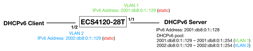
Configuration for DHCPv6 relay:
!
interface ethernet 1/1

!
interface ethernet 1/2
 switchport allowed vlan add 2 untagged
 switchport mode access
 switchport native vlan 2
 switchport allowed vlan remove 1

!
interface vlan 2
 ipv6 dhcp relay destination 2001:db8:0:1::128
!
interface vlan 1
 ipv6 address 2001:db8:0:1::129/64
!
interface vlan 2
 ipv6 address 2002:db8:0:1::129/64
!
DHCPv6 relay packet forwarding procedures:
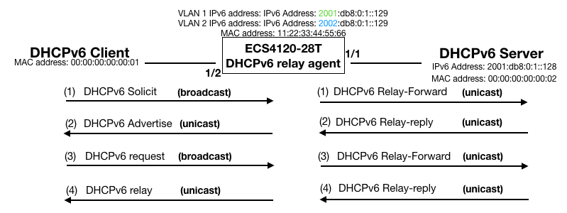
Capture the packets on the port 2. (DHCPv6 Client)
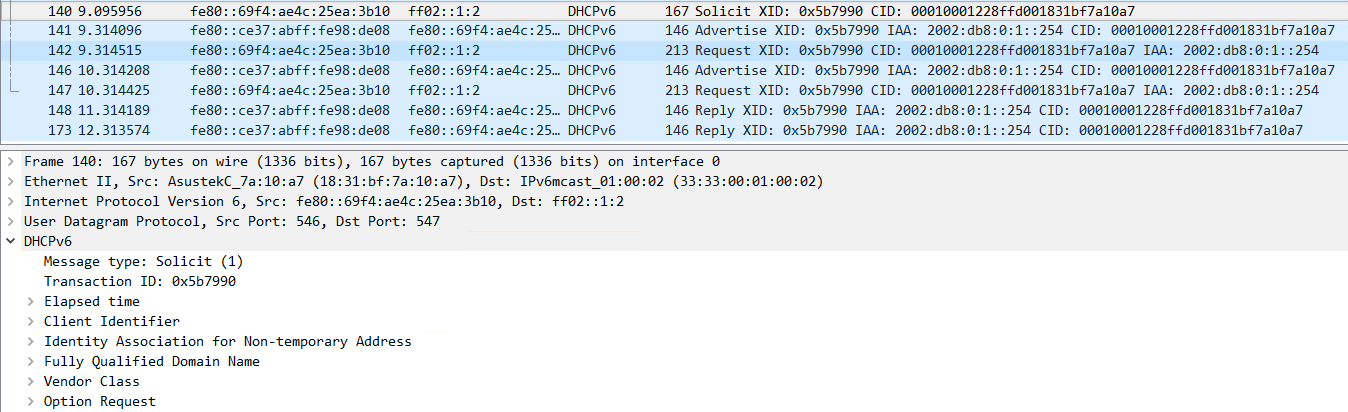
Capture the packets on the port 1. (DHCPv6 Server)
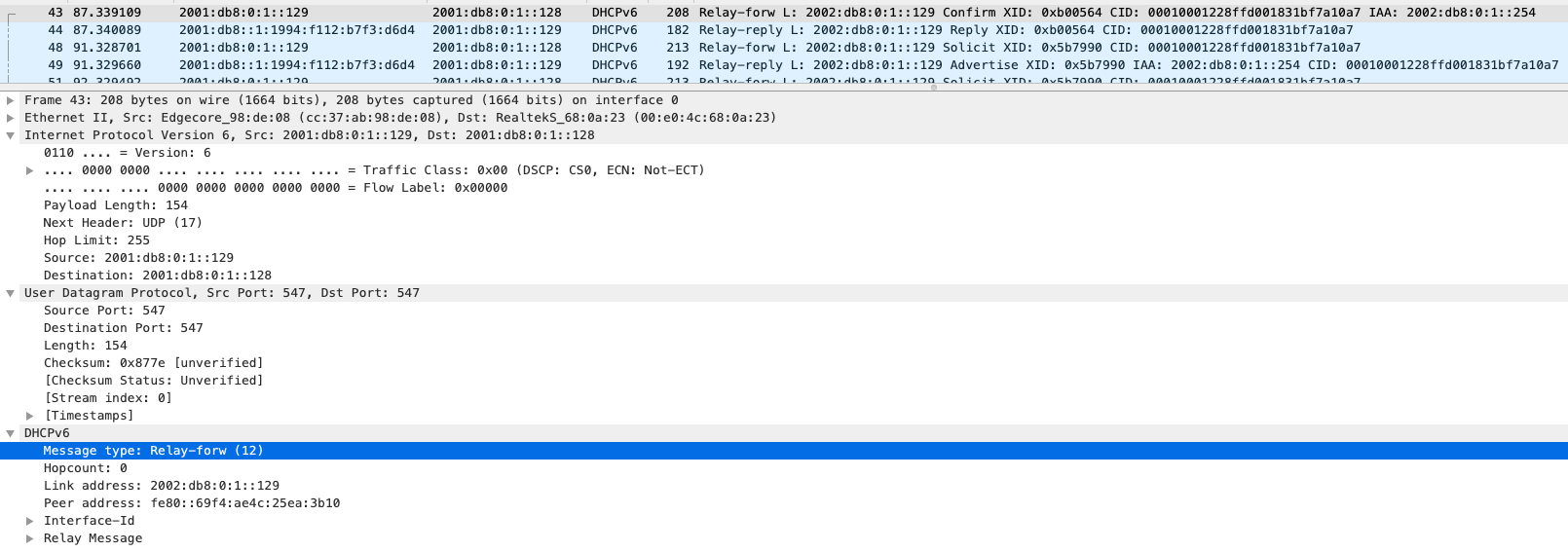
In this example, the client will get the IPv6 address in the range of 2002:db8:0:1::129 ~ 2002:db8:0:1::254 from the DHCP server.
To enable the query function on SW1, use the following steps:

Step 1. Use the command "SW_1(config)#ip igmp snooping query"
Step2. Use 'show IP IGMP Snooping' command to check the status of Query function
SW_1#sh ip igmp snooping
IGMP Snooping : Enabled
Router Port Expire Time : 300 s
Router Alert Check : Disabled
Router Port Mode : Forward
TCN Flood : Disabled
TCN Query Solicit : Disabled
Unregistered Data Flood : Disabled
802.1p Forwarding Priority : Disabled
Unsolicited Report Interval : 400 s
Version Exclusive : Disabled
Version : 2
Proxy Reporting : Disabled
Query : Enabled
VLAN 1:
--------
IGMP Snooping : Enabled
IGMP Snooping Running Status : Active
Version : Using global Version (2)
Version Exclusive : Using global status (Disabled)
Immediate Leave : Disabled
Last Member Query Interval : 10 (unit: 1/10s)
Last Member Query Count : 2
General Query Suppression : Disabled
Query Interval : 125
Query Response Interval : 100 (unit: 1/10s)
Proxy Query Address : 0.0.0.0
Proxy Reporting : Using global status (Disabled)
Multicast Router Discovery : Disabled
VLAN Static Group Port
---- --------------- --------
After the Query function on SW1 is enabled, the port 28 connected to multicast router is still served as mrouter port until the timer of dynamic mrouter port is expired.
SW_1#sh ip igmp snooping mrouter
VLAN M'cast Router Ports Type Expire
---- ------------------- ------- --------
1 Eth 1/28 Dynamic 0:1:56
After the dynamic mrouter port timer expires, the system automatically selects the smallest IP address in the network as query. According to the figure above, IP address 192.168.1.1 of SW1 is the smallest one in the network, therefore SW1 starts to function as only query.
Since SW1 is the Query, mrouter port is no longer exists.
SW_1#sh ip igmp snooping mrouter
VLAN M'cast Router Ports Type Expire
---- ------------------- ------- --------
The packets below captured from PC2 shows that SW1 sends out IGMP General Query periodically every 125 sec.
When the Query function of SW1 is disabled by the command below, PC2 stops playing video streams due to the lack of mrouter port:
SW_1(config)#no ip igmp snooping query
SW_1(config)#exit
PC2 stops playing video stream because of the lack of mrouter port.
SW_1#sh ip igmp snooping mrouter
VLAN M'cast Router Ports Type Expire
---- ------------------- ------- --------
PC2 does not start receiving multicast traffic until new General query from Multicast router is received by SW1.
SW_1#sh ip igmp snooping mrouter
VLAN M'cast Router Ports Type Expire
---- ------------------- ------- --------
1 Eth 1/28 Dynamic 0:3:45
- When configuring RSPAN source port, an error message 'Failed to configure the RSPAN source at Ethe 1/x' comes out. Why?
Console(config)#rspan session 1 source interface ethernet 1/1
Failed to configure the RSPAN source at Eth 1/1.
Console#sh int sw e 1/1
Information of Eth 1/1
Broadcast Threshold : Enabled, 64 Kbits/second
Multicast Threshold : Disabled
Unknown Unicast Threshold : Disabled
LACP Status : Disabled
Ingress Rate Limit : Disabled, 64 Kbits per second
Egress Rate Limit : Disabled, 100000 Kbits per second
VLAN Membership Mode : Access
Ingress Rule : Disabled
Acceptable Frame Type : All frames
Native VLAN : 2
Priority for Untagged Traffic : 0
GVRP Status : Disabled
Allowed VLAN : 2(u)
Forbidden VLAN :
802.1Q Tunnel Status : Disabled
802.1Q Tunnel Mode : Normal
802.1Q Tunnel TPID : 8100 (Hex)
Layer 2 Protocol Tunnel : None
Only 802.1Q trunk or hybrid (i.e., general use) ports can be configured
as an RSPAN uplink or destination port - access ports are not allowed
Console#config
Console(config)#int e 1/1
Console(config-if)#switchport mode hybrid
Console(config-if)#exit
Console(config)#rspan session 1 source interface ethernet 1/1
Console#sh interfaces switchport ethernet 1/1
Information of Eth 1/1
Broadcast Threshold : Enabled, 64 Kbits/second
Multicast Threshold : Disabled
Unknown Unicast Threshold : Disabled
LACP Status : Disabled
Ingress Rate Limit : Disabled, 64 Kbits per second
Egress Rate Limit : Disabled, 100000 Kbits per second
VLAN Membership Mode : Hybrid
Ingress Rule : Disabled
Acceptable Frame Type : All frames
Native VLAN : 2
Priority for Untagged Traffic : 0
GVRP Status : Disabled
Allowed VLAN : 2(u)
Forbidden VLAN :
802.1Q Tunnel Status : Disabled
802.1Q Tunnel Mode : Normal
802.1Q Tunnel TPID : 8100 (Hex)
Layer 2 Protocol Tunnel : None
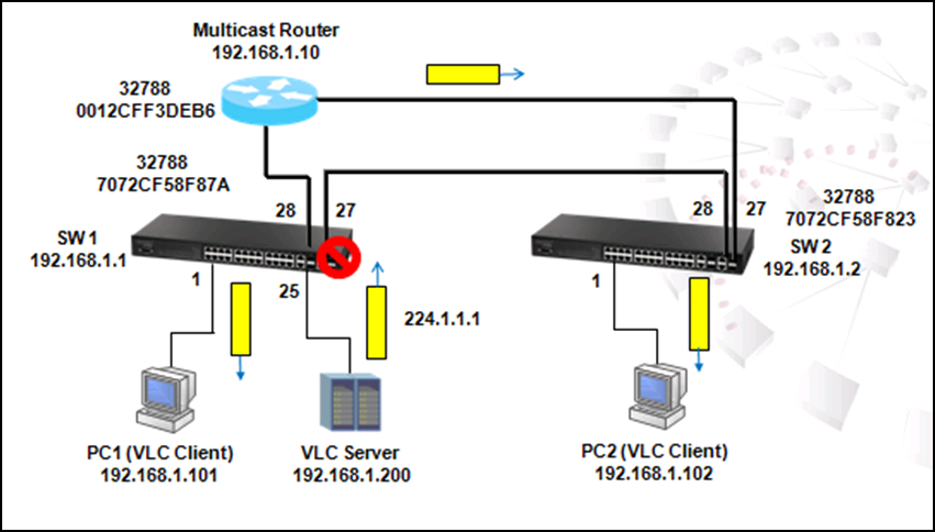
In a ring topology scenario showing above, the spanning tree protocol is enabled by default and SW1 port 27 is the alternative port. Multicast traffic goes through SW1 port 28 to multicast router and then goes to SW2 port 27 and PC2.
If SW2 port 27 is disconnected, the topology will change and the multicast traffic will go from SW1 port 27 to SW2 port 28 and then PC2.
In this way, the multicast registration table in SW2 will be flushed and port 27 is no longer a mrouter port.
The multicast stream stops forwarding to PC2 until SW2 port 28 becomes mrouter port after receiving general query from multicast router and PC2 sends out membership report after receiving general query.
The time for topology recover depends on the time of multicast router sending out general query after receiving topology change notification as well as the time of membership report sent from PC2 responding to general query.
If ES3528MV2 act as a multicast router, it will send out general query immediately after receiving TCN and the maximum response time will be changed from 10s by default to 1s in order to reduce the impact of TCN on multicast streaming.
After the disconnection of SW1 port 28, video stream stops for a while until general query from multicast router has been received and membership report has been sent from PC1.
The packet captured below shows the actions taken during TCN.
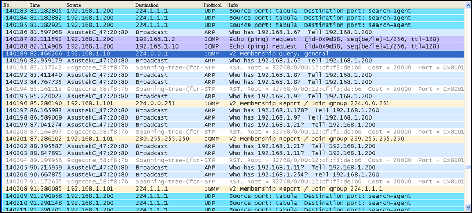
SW_1(config)#ip igmp snooping vlan 1 mrouter ethernet 1/28
SW_1(config)#end
SW_1#sh ip igmp snooping mrouter
VLAN M'cast Router Ports Type Expire
---- ------------------- ------- --------
1 Eth 1/28 Static
Port 28 functions as mrouter port.
SW_1#sh ip igmp snooping group
Bridge Multicast Forwarding Entry Count:1
Flag: R - Router port, M - Group member port
H - Host counts (number of hosts join the group on this port).
P - Port counts (number of ports join the group).
Up time: Group elapsed time (d:h:m:s).
Expire : Group remaining time (m:s).
VLAN Group Port Up time Expire Count
---- --------------- ----------- ----------- ------ --------
1 224.1.1.1 1(P)
Eth 1/28(R)
SW_1#sh ip igmp snooping group
Bridge Multicast Forwarding Entry Count:1
Flag: R - Router port, M - Group member port
H - Host counts (number of hosts join the group on this port).
P - Port counts (number of ports join the group).
Up time: Group elapsed time (d:h:m:s).
Expire : Group remaining time (m:s).
VLAN Group Port Up time Expire Count
---- --------------- ----------- ----------- ------ --------
1 224.1.1.1 02:48 1(P)
Eth 1/28(R)
When a port receives a general query, it will become mrouter port dynamically and the timer will start to count down from 300s (5 min). After 5 minutes, if there is no general query is received by mrouter again, the port will not be mrouter port anymore.
SW_1#show ip igmp snooping mrouter
VLAN M'cast Router Ports Type Expire
---- ------------------- ------- --------
1 Eth 1/28 Dynamic 0:4:39
To change the mrouter port expire timer, use the following command:
SW_1(config)#ip igmp snooping router-port-expire-time?
<1-65535> Time interval of router port expire time (Default: 300)

The figure above shows the scenario that multicast traffic does not flow to all ports in the networks. By following steps we can figure out why VCL client does not receive multicast traffic from VCL server.
Step 1. Check IGMP Snooping function and IGMP Snooping Running Status by the command 'show IP IGMP Snooping.' Please note that IGMP Snooping functions only when IGMP Snooping is enabled and IGMP Running Status is active.
SW_1#show ip igmp snooping
IGMP Snooping : Enabled
Router Port Expire Time : 300 s
Router Alert Check : Disabled
Router Port Mode : Forward
TCN Flood : Disabled
TCN Query Solicit : Disabled
Unregistered Data Flood : Disabled
802.1p Forwarding Priority : Disabled
Unsolicited Report Interval : 400 s
Version Exclusive : Disabled
Version : 2
Proxy Reporting : Disabled
Querier : Disabled
VLAN 1:
--------
IGMP Snooping : Enabled
IGMP Snooping Running Status : Inactive
Version : Using global Version (2)
Version Exclusive : Using global status (Disabled)
Immediate Leave : Disabled
Last Member Query Interval : 10 (unit: 1/10s)
Last Member Query Count : 2
General Query Suppression : Disabled
Query Interval : 125
Query Response Interval : 100 (unit: 1/10s)
Proxy Query Address : 0.0.0.0
Proxy Reporting : Using global status (Disabled)
Multicast Router Discovery : Disabled
VLAN Static Group Port
---- --------------- --------
As shown in the configuration above, IGMP snooping function is enabled but IGMP Snooping Running Status is Inactive.
Step 2. Check Multicast router function in SW1 by the command 'show IP IGMP snooping mrouter'
SW_1#show ip igmp snooping mrouter
VLAN M'cast Router Ports Type Expire
---- ------------------- ------- --------
The configuration shows there is no any multicast router in SW1. It is necessary to have a Multicast Router to control IGMP. Multicast Router controls IGMP by sending out IGMP General Query periodically to solicit receivers who want to join the multicast group and sending Group Specific Query after receiving 'leave messages' to make sure any other receivers remains in that multicast group etc.
Step 3. Check if IP IGMP Snooping Group is grouped by Multicast router by the command 'show IP IGMP Snooping Group:'
SW_1#show ip igmp snooping group
Bridge Multicast Forwarding Entry Count:1
Flag: R - Router port, M - Group member port
H - Host counts (number of hosts join the group on this port).
P - Port counts (number of ports join the group).
Up time: Group elapsed time (d:h:m:s).
Expire : Group remaining time (m:s).
VLAN Group Port Up time Expire Count
---- --------------- ----------- ----------- ------ --------
1 224.1.1.1 01:00 0(P)
ITU-T G.8032 Ethernet Ring Protection Switching (ERPS) is a function that enables the network to detect and recover from link failure without impacting users and meets the most demanding high reliability and continuous availability requirement.
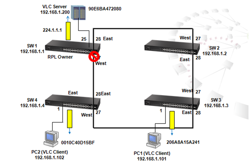
The scenario shown above is an example showing how ERPS works.
To enable ERPS, use the following commands:
1. Disable STP function on port 27 and 28 of Each Switch in the loop
SW_1(config)#int e 1/27-28
SW_1(config-if)#spanning-tree spanning-disabled
For enable ERPS function on specific ports, STP needs to be disabled. In this case, STP should be disabled on port 27 and 28 of each switch. Apart from port 27 and 28, STP still functions on other ports to prevent loop.
2. Enable ERPS function on each switch
SW_1(config)#erps
3. Create ERPS domain name on each switch, for example "Edge-Core"
SW_1(config)#erps domain Edge-Core
4. Configure west port on port 27 and east port on port 28
SW_1(config-erps)#ring-port west interface ethernet 1/27
SW_1(config-erps)#ring-port east interface ethernet 1/28
5. Configure SW1 as RPL owner. Please note that only RPL owner needs to be configured.
SW_1(config-erps)#rpl owner
6. Configure and enable control vlan on each switch, for example vlan 1
SW_1(config-erps)#control-vlan 1
7. Enable ERPS domain. Please note that ERPS cannot be enabled unless steps 3-6 are completed.
SW_1(config-erps)#enable

To check IGMP Snooping statistic report, use the command "clear IP IGMP snooping statistics."
SW_1#clear ip igmp snooping statistics
Use the command 'show IP IGMP Snooping statistics input interface Ethernet 1/x ' to check Leave, General Query, Group specific Query, Drop, Join Success, Group statistic reports of each port.
SW_1#sh ip igmp snooping statistics input interface ethernet 1/25
Input Statistics:
Interface Report Leave G Query G(-S)-S Query Drop Join Succ Group
--------- -------- -------- -------- ------------- -------- --------- -----------
Eth 1/25 42 0 0 0 14 28 2
As shown above, there are 42 IGMP reports received by port 25 connected to VLC Server. 14 packets are dropped,28 packets register to the multicast table successfully, and 2 multicast groups.
Use the command 'show IP IGMP Snooping statistics output interface Ethernet 1/x' to check Leave, General Query, Group specific Query statistic reports of each port.
SW_1#sh ip igmp snooping statistics output interface ethernet 1/25 Output Statistics:
Interface Report Leave G Query G(-S)-S Query
--------- -------- -------- -------- -------------
Eth 1/25 0 0 14 0
As shown above, there are 0 IGMP report, 0 leaves, 14 General Queries send out from port 25 connected to VLC Server
Use the command 'show IP IGMP Snooping statistics Query' to check General statistic report.
SW_1#sh ip igmp snooping statistics query
VLAN 1
Querier IP Address : 192.168.1.10
Querier Expire Time : 00(h):02(m):57(s)
General Query Received : 14
General Query Sent : 14
Specific Query Received : 8
Specific Query Sent : 8
Number of Reports Sent : 90
Number of Leaves Sent : 4
SW_1#sh ip igmp snooping group
Bridge Multicast Forwarding Entry Count:3
Flag: R - Router port, M - Group member port
H - Host counts (number of hosts join the group on this port).
P - Port counts (number of ports join the group).
Up time: Group elapsed time (d:h:m:s).
Expire : Group remaining time (m:s).
VLAN Group Port Up time Expire Count
---- --------------- ----------- ----------- ------ --------
1 224.0.1.75 00:00:07:12 2(P)
Eth 1/25(M) 00:00:07:12 03:08 1(H)
Eth 1/28(R)
1 239.255.255.250 00:00:07:28 3(P)
Eth 1/ 1(M) 00:00:07:19 03:08 1(H)
Eth 1/27(M) 00:00:07:28 03:14 1(H)
Eth 1/28(R)
1 239.255.255.254 00:00:07:11 2(P)
Eth 1/25(M) 00:00:07:11 03:14 1(H)
Eth 1/28(R)
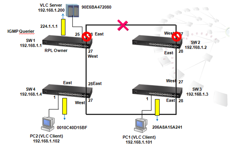
The figure above is a scenario when a link failure occurs. As shown above, when a link failure occurs between port 28 of SW1 and port 27 of SW2, ERPS will automatically function. When ERPS functions, the state of port 27 of SW1 will change from blocking to connecting and the port 27 of SW1 will become forwarding less then 50msec. The switch is under Protection mode. It applies to each switch in this network.
Use command "SW_1#sh erps" to check the state of each switch:
SW_1#sh erps
ERPS Status : Enabled
Number of ERPS Domains : 1
Domain State MEL Enabled West East RPL Owner Ctrl VLAN
------------ ---------- --- ------- -------- -------- --------- ---------
Edge-Core Protection 1 Yes Eth 1/27 Eth 1/28 Yes 1
SW_1#sh erps domain Edge-Core
Domain Name : Edge-Core
Admin Status : Enabled
MEG Level : 1
Node ID : 70-72-CF-58-F9-0B
Node State : Protection
West Port : Eth 1/27 (Forwarding)
East Port : Eth 1/28 (Blocking)
RPL Port : West
RPL Owner : Enabled
Holdoff Timer : 0 ms
Guard Timer : 500 ms
WTR Timer : 5 minutes
Control VLAN : 1
Non-ERPS Device Protect : Disabled
Propagate TC : Disabled
SW_1#telnet 192.168.1.2
If the link between port 28 of SW1 and port 27 of SW2 is reconnected, port 28 of SW1 and port 27 of SW2 remained in blocking state.
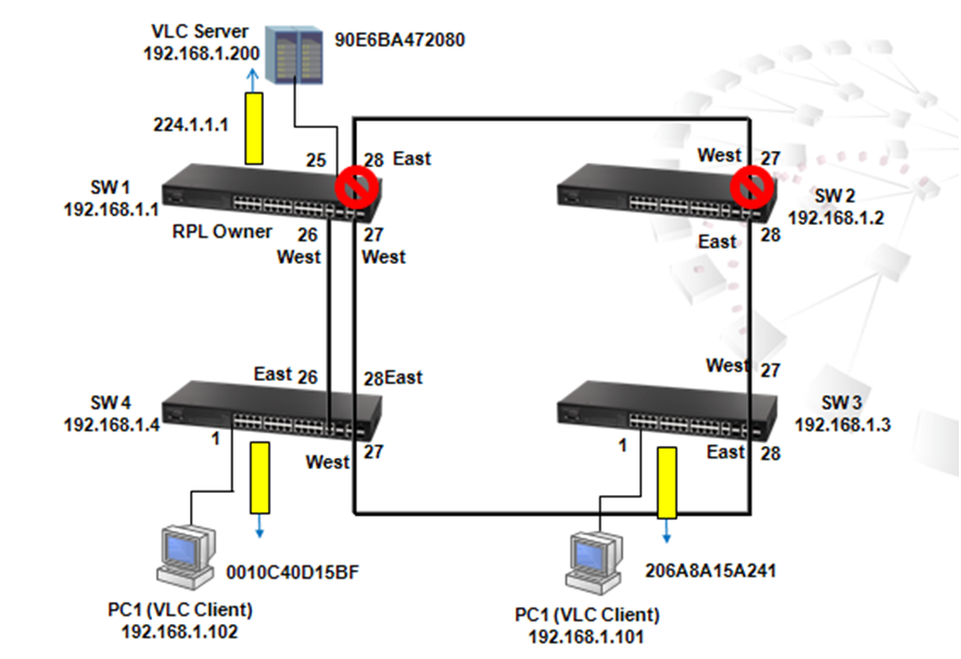
After WTR Timer 5 minutes, west port 27 goes back to blocking, port 28 becomes forwarding, and the status of SW1 changes back to Idle mode.
SW_1#sh erps domain Edge-Core
Domain Name : Edge-Core
Admin Status : Enabled
MEG Level : 1
Node ID : 70-72-CF-58-F9-0B
Node State : Idle
West Port : Eth 1/27 (Blocking)
East Port : Eth 1/28 (Forwarding)
RPL Port : West
RPL Owner : Enabled
Holdoff Timer : 0 ms
Guard Timer : 500 ms
WTR Timer : 5 minutes
Control VLAN : 1
Non-ERPS Device Protect : Disabled
Propagate TC : Disabled
IGMP Filter function is normally used by Service Provider to control the channels that users subscribed to. To enable IP IGMP Filter, use the following steps:
Step 1. Use the command "IP IGMP Filter"
SW_1(config)#ip igmp filter
Step 2. Create IP IGMP profile 1. Only multicast group from range 224.1.1.1 to 224.1.1.3 is permitted
SW_1(config)#ip igmp profile 1
SW_1(config-igmp-profile)#permit
SW_1(config-igmp-profile)#range 224.1.1.1 224.1.1.3
Step 3. Check the configuration
SW_1#sh ip igmp filter
IGMP Filter Enabled
SW_1#sh ip igmp profile
IGMP Profile 1
SW_1#sh ip igmp profile 1
IGMP Profile 1
Permit
Range 224.1.1.1 224.1.1.3
Step 4. Apply IGMP filter profile 1 to port
SW_1(config)#int e 1/27
SW_1(config-if)#ip igmp filter 1
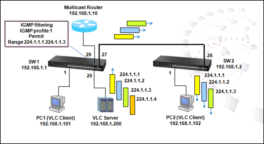
After IGMP filter profile 1 is applied to port 27, PC2 receives video stream from 224.1.1.1 to 3 only.
Please note that because IMGP filter blocks out the membership report packet of profile, PC2 receives video stream from 224.1.1.4 until "entry in multicast table time" is expiring.
SW_1#sh ip igmp snooping group
Bridge Multicast Forwarding Entry Count:7
Flag: R - Router port, M - Group member port
H - Host counts (number of hosts join the group on this port).
P - Port counts (number of ports join the group).
Up time: Group elapsed time (d:h:m:s).
Expire : Group remaining time (m:s).
VLAN Group Port Up time Expire Count
---- --------------- ----------- ----------- ------ --------
1 224.0.1.75 00:00:34:45 2(P)
Eth 1/25(M) 00:00:34:45 03:54 1(H)
Eth 1/28(R)
1 224.1.1.1 00:00:00:16 2(P)
Eth 1/27(M) 00:00:00:16 04:05 1(H)
Eth 1/28(R)
1 224.1.1.2 00:00:25:59 2(P)
Eth 1/27(M) 00:00:25:59 03:55 1(H)
Eth 1/28(R)
1 224.1.1.3 00:00:25:39 2(P)
Eth 1/27(M) 00:00:25:39 03:51 1(H)
Eth 1/28(R)
1 224.1.1.4 00:24 1(P)
Eth 1/28(R)
1 239.255.255.250 00:00:34:41 2(P)
Eth 1/ 1(M) 00:00:21:13 03:48 1(H)
Eth 1/28(R)
1 239.255.255.254 00:00:34:43 2(P)
Eth 1/25(M) 00:00:34:43 03:56 1(H)
Eth 1/28(R)
115 ES3528MV2 Supports CFM - When to use IEEE 802.1ag Connectivity Fault Management and ITU-T Y.1731?
The Layer 2 network that is managed will be divided into different Maintenance Domains. A maintenance domain (MD) is an administrative domain for managing and administering a network. The Maintenance Domain provides management and hierarchy. A domain is assigned a unique maintenance level (up to 8) by the administrator.
The figure below is an example of the application of CFM. Four switches SW1 to SW4 are directly connected in a linear topology. SW3 and SW4 devices from Operator and SW1 and SW2 are devices from Operator who provide service to Provider.
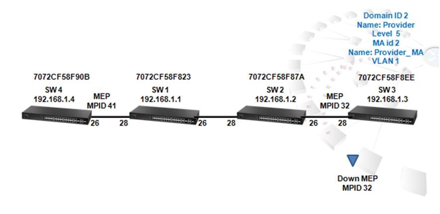
IGMP throttling normally is used by service providers to control the quantities of channels that could be subscribed by users at one time. By doing this, service providers prevent users from attaching to too many hosts without be charged and from wasting the bandwidth.
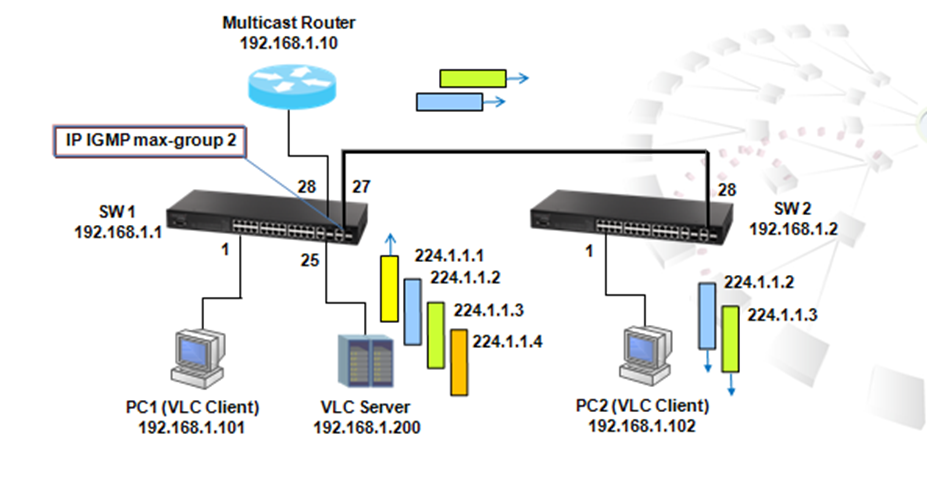
Step 1. Enter interface 27 and configure igmp max-groups to 2. After two multicast groups learned this port, other join packets will be discarded by port 27. Configuration status is as follow:
SW_1(config)#interface e 1/27
SW_1(config-if)#ip igmp max-groups 2
SW_1(config-if)#ip igmp max-groups action deny
Step 2. Check the configuration
SW_1#sh ip igmp throttle interface e 1/27
Eth 1/27 Information
Status : TRUE
Action : Deny
Max Multicast Groups : 2
Current Multicast Groups : 2
From the multicast registration table shown below, it is clear that only 224.1.1.2 and 224.1.1.3 are learned by PC2, and therefore PC2 plays video streams transmitted from these two groups only.
SW_1#sh ip igmp snooping group
Bridge Multicast Forwarding Entry Count:7
Flag: R - Router port, M - Group member port
H - Host counts (number of hosts join the group on this port).
P - Port counts (number of ports join the group).
Up time: Group elapsed time (d:h:m:s).
Expire : Group remaining time (m:s).
VLAN Group Port Up time Expire Count
---- --------------- ----------- ----------- ------ --------
1 224.0.1.75 00:00:52:00 2(P)
Eth 1/25(M) 00:00:52:00 03:21 1(H)
Eth 1/28(R)
1 224.1.1.1 02:57 1(P)
Eth 1/28(R)
1 224.1.1.2 00:00:43:13 2(P)
Eth 1/27(M) 00:00:43:13 03:19 1(H)
Eth 1/28(R)
1 224.1.1.3 00:00:42:53 2(P)
Eth 1/27(M) 00:00:42:53 03:21 1(H)
Eth 1/28(R)
1 224.1.1.4 01:11 1(P)
Eth 1/28(R)
1 239.255.255.250 00:00:51:55 2(P)
Eth 1/ 1(M) 00:00:38:27 03:16 1(H)
Eth 1/28(R)
1 239.255.255.254 00:00:51:57 2(P)
Eth 1/25(M) 00:00:51:57 03:17 1(H)
Eth 1/28(R)
When IGMP throttling is enabled, the ip igmp max-groups action is "deny." There is another action "replace:"
SW_1(config)#int e 1/27
SW_1(config-if)#ip igmp max-groups action replace
SW_1#sh ip igmp snooping group
Bridge Multicast Forwarding Entry Count:7
Flag: R - Router port, M - Group member port
H - Host counts (number of hosts join the group on this port).
P - Port counts (number of ports join the group).
Up time: Group elapsed time (d:h:m:s).
Expire : Group remaining time (m:s).
VLAN Group Port Up time Expire Count
---- --------------- ----------- ----------- ------ --------
1 224.0.1.75 00:00:55:02 2(P)
Eth 1/25(M) 00:00:55:02 02:18 1(H)
Eth 1/28(R)
1 224.1.1.1 00:00:00:34 2(P)
Eth 1/27(M) 00:00:00:34 03:47 1(H)
Eth 1/28(R)
1 224.1.1.2 02:25 1(P)
Eth 1/28(R)
1 224.1.1.3 00:00:45:55 2(P)
Eth 1/27(M) 00:00:45:55 02:23 1(H)
Eth 1/28(R)
1 224.1.1.4 01:08 1(P)
Eth 1/28(R)
1 239.255.255.250 00:00:54:58 2(P)
Eth 1/ 1(M) 00:00:41:29 02:21 1(H)
Eth 1/28(R)
1 239.255.255.254 00:00:54:59 2(P)
Eth 1/25(M) 00:00:54:59 02:19 1(H)
Eth 1/28(R)
If the action is "Replace", the latest report will replace the previous one.
117 ES3528MV2 Supports CFM - How to use IEEE 802.1ag Connectivity Fault Management and ITU-T Y.1731?

Step1. On Switch 3, create CFM maintenance Domain (MD). The index is 2, name is character string "Provider," and the MD level 5
SW_3-0#config
SW_3-0(config)#ethernet cfm domain index 2 name Provider level 5
Step2. Create Maintenance Association (MA) service in MD "Provider." The MD ID is 2, name is "Provider_MA," and service VLAN identifier is "1."
SW_3-0(config-ether-cfm)#ma index 2 name Provider_MA vlan 1
Step3. Configure MEP crosscheck with mpid 41 on SW 4 ma "Provider_MA." try7711***The Cross Check List for a MD contains a list of MEPID (Maintenance End Point Identifier) which are configured in a MA.
SW_3-0(config-ether-cfm)#mep crosscheck mpid 41 ma Provider_MA
SW_3-0(config-ether-cfm)#exit
Step4. Create mep mpid 32 on port 28 of SW3
Maintenance End Point (MEP) generates and responds to CFM PDUs. A MEP can be uniquely identified by Maintenance Level, VLAN ID and Direction. Direction is of two types, UP and Down, and denotes the direction in which the MEP faces on the Bridge port. The default direction is Down.
When MEP (Maintenance End Point) is configured in a Switch, it is called Local MEP. The other MEP ID which is present in the cross-check list becomes Remote MEP for this Local MEP.
SW_3-0(config)#int e 1/28
SW_3-0(config-if)#ethernet cfm mep mpid 32 md Provider ma Provider_MA
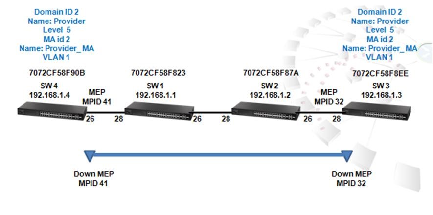
Step5. On Switch 2, create the same CFM domain ID 2 name "Provider" level 5 in level 5 in SW4 as SW3
SW_4-0#config
SW_4-0(config)#ethernet cfm domain index 2 name Provider level 5
Step6. Create MA id 2 name "Provider_MA" on vlan 1
SW_4-0(config-ether-cfm)#ma index 2 name Provider_MA vlan 1
Step7. Configure MEP crosscheck with mpid 32 on SW 3 ma Provider_MA
SW_4-0(config-ether-cfm)#mep crosscheck mpid 32 ma Provider_MA
Step8. Create mep mpid 41 on port 26 of SW4
SW_4-0(config)#interface e 1/26
SW_4-0(config-if)#ethernet cfm mep mpid 41 md Provider ma Provider_MA
Step9. Show local MEP on SW4
SW_4-0#sh ethernet cfm maintenance-points local detail mep
MEP Settings:
-------------
MPID : 41
MD Name : Provider
MA Name : Provider_MA
MA Name Format : Character String
Level : 5
Direction : Down
Interface : Eth 1/26
CC Status : Enabled
MAC Address : 70-72-CF-58-F9-25
Defect Condition : No Defect
Received RDI : False
AIS Status : Enabled
AIS Period : 1 seconds
AIS Transmit Level : Default (0)
Suppress Alarm : Disabled
Suppressing Alarms : Disabled
Step10. Show remote crosscheck list
SW_4-0#sh ethernet cfm maintenance-points remote crosscheck
MPID MA Name Level VLAN MEP Up Remote MAC
------- ----------------------- --------- ---- ---------- -----------------
32 Provider_MA 5 1 Yes 70-72-CF-58-F9-0A
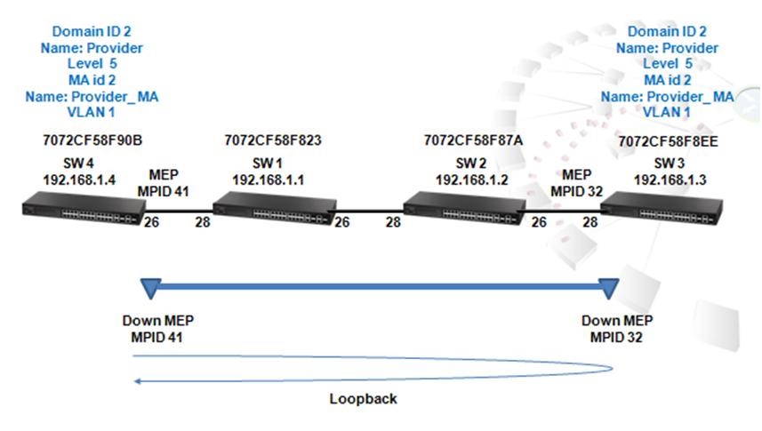
Step11. Initiate CFM loopback to MEP 32 of SW3
Loopback is used for connection verification between two Maintenance End Points. Loopback can be identified by specifying the destination MEP MAC address or MEP ID.
SW_4-0#ethernet cfm loopback dest-mep 32 md Provider ma Provider_MA
Type ESC to abort.
Sending 5 Ethernet CFM loopback message, timeout is 5 sec.
Received 5 Ethernet CFM loopback message in 1 sec.
Received 5 Ethernet CFM loopback message in 5 secs.
Success rate is 100% (5/5).
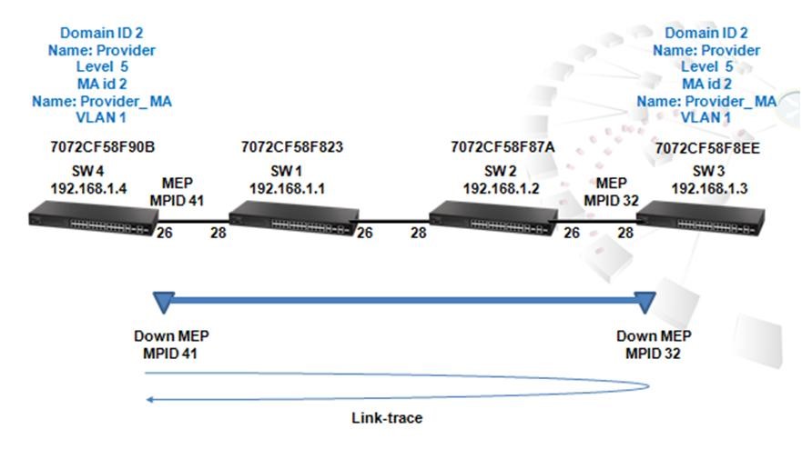
Figure 4
Step12. Initiate CFM Linktrace to SW3 MEP 32
Linktrace is used by a maintenance entity to perform path discovery and fault isolation.
SW_4-0#ethernet cfm linktrace dest-mep 32 md Provider ma Provider_MA
SW_4-0#sh ethernet cfm linktrace-cache
Hops MA IP / Alias Ingress MAC Ing. Action Relay
Forwarded Egress MAC Egr. Action
--------- ---------------- ----------------------- ---------------------- ------------------ -------------
1 Provider_MA 192.168.1.3 70-72-CF-58-F9-0A ingOk Hit
Not Forwarded
Step13. Show local MEP on SW3
SW_3-0#sh ethernet cfm maintenance-points local detail mep
MEP Settings:
-------------
MPID : 32
MD Name : Provider
MA Name : Provider_MA
MA Name Format : Character String
Level : 5
Direction : Down
Interface : Eth 1/28
CC Status : Enabled
MAC Address : 70-72-CF-58-F9-0A
Defect Condition : No Defect
Received RDI : False
AIS Status : Enabled
AIS Period : 1 seconds
AIS Transmit Level : Default (0)
Suppress Alarm : Disabled
Suppressing Alarms : Disabled
Step14. Show remote crosscheck on SW3
SW_3-0#sh ethernet cfm maintenance-points remote crosscheck
MPID MA Name Level VLAN MEP Up Remote MAC
-------- ------------------------ ------ -------- ----------- -----------------
41 Provider_MA 5 1 Yes 70-72-CF-58-F9-25
Step15. Initiate CFM loopback to SW4 MEP 41
SW_3-0#ethernet cfm loopback dest-mep 41 md Provider ma Provider_MA
Type ESC to abort.
Sending 5 Ethernet CFM loopback message, timeout is 5 sec.
Received 5 Ethernet CFM loopback message in 1 sec.
Received 5 Ethernet CFM loopback message in 5 secs.
Success rate is 100% (5/5).
Step16. Initiate CFM Linktrace to SW3 MEP 32
SW_3-0#ethernet cfm linktrace dest-mep 41 md Provider ma Provider_MA
SW_3-0#sh ethernet cfm linktrace-cache
Hops MA IP / Alias Ingress MAC Ing. Action Relay
Forwarded Egress MAC Egr. Action
------ ----------------- ----------------------- ------------------------ --------------------- -----------
1 Provider_MA 192.168.1.4 70-72-CF-58-F9-25 ingOk Hit
Not Forwarded
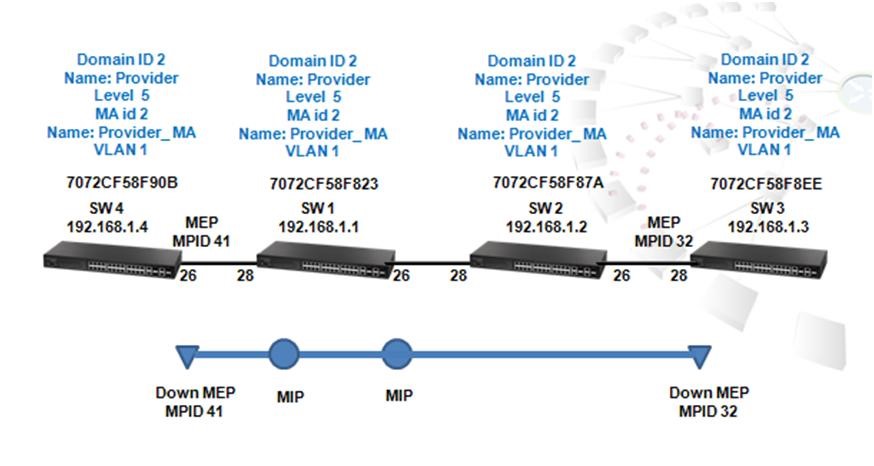
Figure 5
Step17. On Switch 1, create CFM domain ID 2 name Provider level 5
SW_1#config
SW_1(config)#ethernet cfm domain index 2 name Provider level 5
Step18. Create MA id 2 name Provider_MA on vlan 1
SW_1(config-ether-cfm)#ma index 2 name Provider_MA vlan 1
Step19. MIP will be generated by default.
Maintenance Intermediate Points (MIP) are intermediate maintenance points which forward CFM PDUs. MIPs are implicitly created.
SW_1#sh ethernet cfm maintenance-points local mip
MD Name Level MA Name VLAN Interface
----------------------- -------- ----------------------- ---------------- ----------------------
Provider 5 Provider_MA 1 Eth 1/ 1
Provider 5 Provider_MA 1 Eth 1/ 2
Provider 5 Provider_MA 1 Eth 1/ 3
Provider 5 Provider_MA 1 Eth 1/ 4
Provider 5 Provider_MA 1 Eth 1/ 5
Provider 5 Provider_MA 1 Eth 1/ 6
Provider 5 Provider_MA 1 Eth 1/ 7
Provider 5 Provider_MA 1 Eth 1/ 8
Provider 5 Provider_MA 1 Eth 1/ 9
Provider 5 Provider_MA 1 Eth 1/10
Provider 5 Provider_MA 1 Eth 1/11
Provider 5 Provider_MA 1 Eth 1/12
Provider 5 Provider_MA 1 Eth 1/13
Provider 5 Provider_MA 1 Eth 1/14
Provider 5 Provider_MA 1 Eth 1/15
Provider 5 Provider_MA 1 Eth 1/16
Provider 5 Provider_MA 1 Eth 1/17
Provider 5 Provider_MA 1 Eth 1/18
Provider 5 Provider_MA 1 Eth 1/19
Provider 5 Provider_MA 1 Eth 1/20
Provider 5 Provider_MA 1 Eth 1/21
Provider 5 Provider_MA 1 Eth 1/22
Provider 5 Provider_MA 1 Eth 1/23
Provider 5 Provider_MA 1 Eth 1/24
Provider 5 Provider_MA 1 Eth 1/25
Provider 5 Provider_MA 1 Eth 1/26
Provider 5 Provider_MA 1 Eth 1/27
Provider 5 Provider_MA 1 Eth 1/28
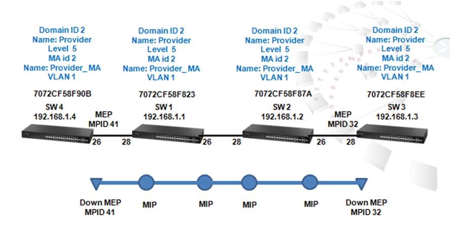
Figure 6
Step20. On Switch 2, create CFM domain ID 2 name Provider level 5
SW_2-0#config
SW_2-0(config)#ethernet cfm domain index 2 name Provider level 5
Step21. Create MA id 2 name "Provider_MA" on vlan 1
SW_2-0(config-ether-cfm)#ma index 2 name Provider_MA vlan 1
Step22. MIP will be generated by default
SW_2-0#sh ethernet cfm maintenance-points local mip
MD Name Level MA Name VLAN Interface
------------------ ---------- ----------------------- ----------- -------------
Provider 5 Provider_MA 1 Eth 1/ 1
Provider 5 Provider_MA 1 Eth 1/ 2
Provider 5 Provider_MA 1 Eth 1/ 3
Provider 5 Provider_MA 1 Eth 1/ 4
Provider 5 Provider_MA 1 Eth 1/ 5
Provider 5 Provider_MA 1 Eth 1/ 6
Provider 5 Provider_MA 1 Eth 1/ 7
Provider 5 Provider_MA 1 Eth 1/ 8
Provider 5 Provider_MA 1 Eth 1/ 9
Provider 5 Provider_MA 1 Eth 1/10
Provider 5 Provider_MA 1 Eth 1/11
Provider 5 Provider_MA 1 Eth 1/12
Provider 5 Provider_MA 1 Eth 1/13
Provider 5 Provider_MA 1 Eth 1/14
Provider 5 Provider_MA 1 Eth 1/15
Provider 5 Provider_MA 1 Eth 1/16
Provider 5 Provider_MA 1 Eth 1/17
Provider 5 Provider_MA 1 Eth 1/18
Provider 5 Provider_MA 1 Eth 1/19
Provider 5 Provider_MA 1 Eth 1/20
Provider 5 Provider_MA 1 Eth 1/21
Provider 5 Provider_MA 1 Eth 1/22
Provider 5 Provider_MA 1 Eth 1/23
Provider 5 Provider_MA 1 Eth 1/24
Provider 5 Provider_MA 1 Eth 1/25
Provider 5 Provider_MA 1 Eth 1/26
Provider 5 Provider_MA 1 Eth 1/27
Provider 5 Provider_MA 1 Eth 1/28
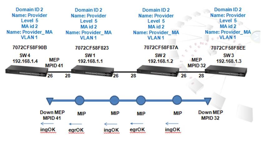
Figure 7
Step23. Initiate CFM Linktrace to SW4 MEP 41, because of the MIPs, we can new the detail path from SW3 to SW4 is via SW 2 and 1.
SW_3-0#EThernet cfm linktrace dest-mep 41 md Provider ma Provider_MA
SW_3-0#sh ethernet cfm linktrace-cache
Hops MA IP / Alias Ingress MAC Ing. Action Relay
Forwarded Egress MAC Egr. Action
---- -------------- ----------------------- ----------------------- ------------------------- -------------
1 Provider_MA 192.168.1.4 70-72-CF-58-F9-25 ingOk Hit
Not Forwarded
1 Provider_MA 192.168.1.2 70-72-CF-58-F8-94 ingOk FDB
Forwarded 70-72-CF-58-F8-96 egrOk
2 Provider_MA 192.168.1.1 70-72-CF-58-F8-3D ingOk FDB
Forwarded 70-72-CF-58-F8-3F egrOk
3 Provider_MA 192.168.1.4 70-72-CF-58-F9-25 ingOk Hit
Not Forwarded
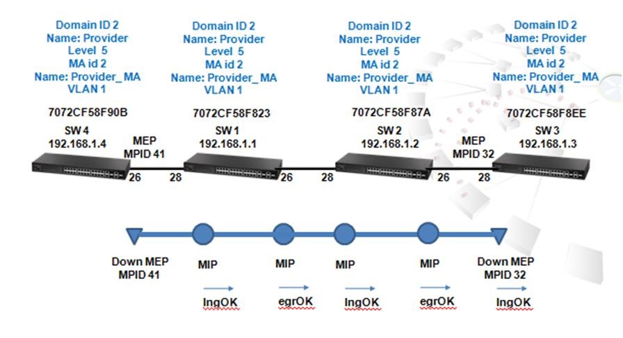
Step24. Initiate CFM Linktrace from SW4 to SW3 remote MEP 32, because of the MIPs, we can new the detail path from SW4 to SW3 is via SW 1 and 2.
SW_4-0#EThernet Cfm linktrace dest-mep 32 md Provider ma Provider_MA
SW_4-0#sh ethernet cfm linktrace-cache
Hops MA IP / Alias Ingress MAC Ing. Action Relay
Forwarded Egress MAC Egr. Action
---- -------------- ----------------------- --------------------- ------------------- --------------
1 Provider_MA 192.168.1.3 70-72-CF-58-F9-0A ingOk Hit
Not Forwarded
1 Provider_MA 192.168.1.3 70-72-CF-58-F9-0A ingOk Hit
Not Forwarded
1 Provider_MA 192.168.1.1 70-72-CF-58-F8-3F ingOk FDB
Forwarded 70-72-CF-58-F8-3D egrOk
2 Provider_MA 192.168.1.2 70-72-CF-58-F8-96 ingOk FDB
Forwarded 70-72-CF-58-F8-94 egrOk
3 Provider_MA 192.168.1.3 70-72-CF-58-F9-0A ingOk Hit
Not Forwarded
How to flow multicast traffic to all ports?
By disabling IP IGMP snooping.
If IP IGMP Snooping function is disabled, SW1 will flood multicast traffic to all ports when a switch port receives broadcast, unknown unicast or multicast.
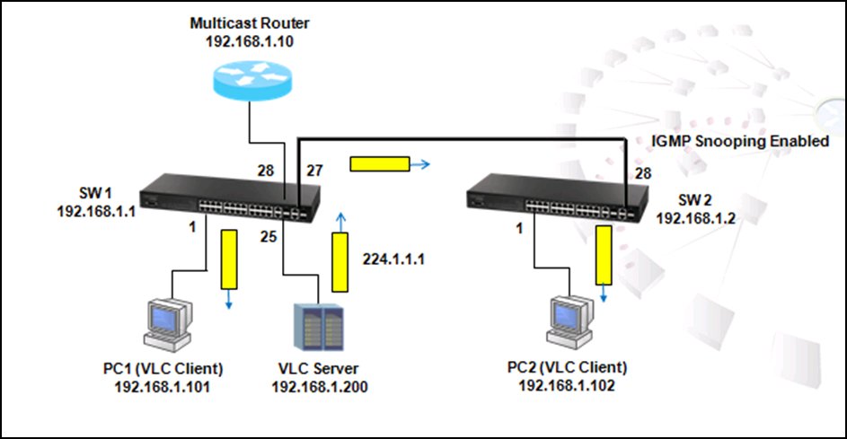
The command to disable IGMP Snooping function:
SW_1#config
SW_1(config)#no ip igmp snooping
After adjusting, PC1 and SW2 receive multicast traffic, but PC2 will not receive multicast traffic since SW2 is still IGMP Snooping enabled by default.
To check IGMP Snooping function status, use 'show IP IGMP snooping' command:
SW_1#show IP IGMP snooping
IGMP Snooping : Disabled
Router Port Expire Time : 300 s
Router Alert Check : Disabled
Router Port Mode : Forward
TCN Flood : Disabled
TCN Query Solicit : Disabled
Unregistered Data Flood : Disabled
802.1p Forwarding Priority : Disabled
Unsolicited Report Interval : 400 s
Version Exclusive : Disabled
Version : 2
Proxy Reporting : Disabled
Querier : Disabled
VLAN 1:
--------
IGMP Snooping : Enabled
IGMP Snooping Running Status : Inactive
Version : Using global Version (2)
Version Exclusive : Using global status (Disabled)
Immediate Leave : Disabled
Last Member Query Interval : 10 (unit: 1/10s)
Last Member Query Count : 2
General Query Suppression : Disabled
Query Interval : 125
Query Response Interval : 100 (unit: 1/10s)
Proxy Query Address : 0.0.0.0
Proxy Reporting : Using global status (Disabled)
Multicast Router Discovery : Disabled
VLAN Static Group Port
---- --------------- --------
To check/display the entries in multicast registration table, use 'show IP IGMP snooping group' command:
SW_1#show ip igmp snooping group
Bridge Multicast Forwarding Entry Count:0
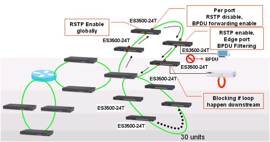
Figure 1
Figure 1 shows the scenario when BPDU function is activated in the ring.
In a ring topology, in order to reduce the convergence time and increase the number of switches in a ring, ISPs configure two connected ports in the ring as "STP disable and BPDU forwarding." When one of the ports configured as "STP disable and BPDU forwarding" receives a BPDU, it will directly forward BPDU out to another port without processing, and eventually the BPDU will come back to the Root switch quickly. When the root switch receives the BPDU sent out by itself on another port, it will block that port in order to prevent loop, and to provide a redundant path if any link failures occurs in the loop.
The BPDU Filter is designed for the port connected to end-user's device with the concept of preventing from receiving BPDU. As service providers, ISPs do not want end-users to see the BPDU that contains the topology information of the ISP network. Therefore, if the edge port is configured as BPDU filtering, BPDU will not be sent out and the end-user will not see the network information.
Multicast is an advanced transmission application that transits information packages from one point to multiple points by sending package once only. Unlike Unicast and Broadcast, when sending information package to multiple Mac addresses under one IP, Multicast will identify those Mac addresses registered to receive a specific info package and send that info to them only instead of to every Mac addresses under IP. In this way, Multicast reduces the heavy volume of traffic and loadings and transits information to specific group members.
It is a most advanced and beneficial feature to on-line paid video-watching program. On-line video providers want to deliver videos to customers who have paid to watch and to avoid videos are flowed to those who do not pay. By using Multicast application, providers could classify their users into several groups according to the videos selected and videos will be delivered to that specific group only.
ES3528MV2 is a newly launched Edgecore's L2 Fast Ethernet Standalone Switch and supports Multicast storm control application. Administrators could use the following steps to configure, monitor and check Multicast function:
How to check if IGMP Snooping function properly?
To use following commands to enable IP IGMP Snooping function:
SW_1#config
SW_1(config)#ip igmp snooping
IGMP snooping functions once a Multicast Router is connected to SW1.
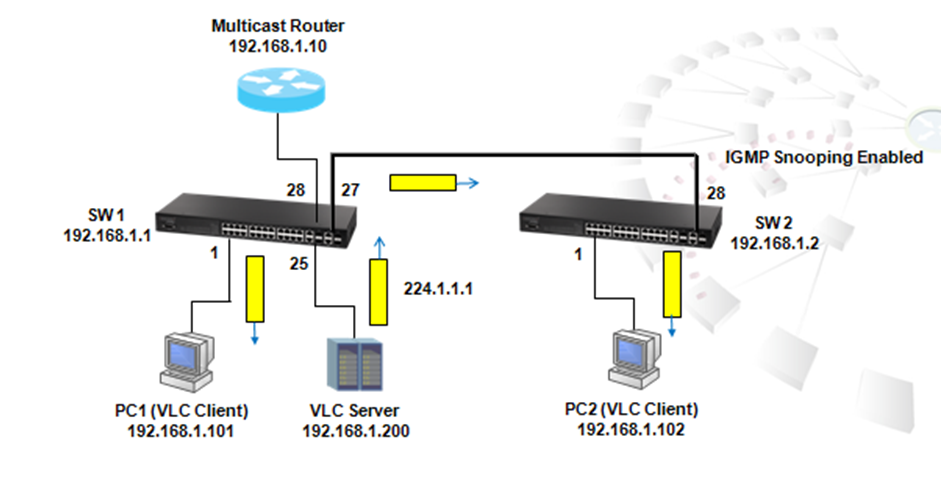
As shown in the figure above, Port 28 of SW1 is connected to Multicast Router and it would be the mrouter port after IGMP general query is received. The Router Port Expire Time is 300 seconds by default.
SW_1#show ip igmp snooping mrouter
VLAN M'cast Router Ports Type Expire
---- ------------------- ------- --------
1 Eth 1/28 Dynamic 0:4:39
Use 'show IP IGMP snooping group' to check if whether multicast group 224.1.1.1 is learned by mrouter port. If the multicast group is learned, multicast traffic destined to 224.1.1.1 will not be flooded to other ports.
SW_1#sh ip igmp snooping group
Bridge Multicast Forwarding Entry Count:1
Flag: R - Router port, M - Group member port
H - Host counts (number of hosts join the group on this port).
P - Port counts (number of ports join the group).
Up time: Group elapsed time (d:h:m:s).
Expire : Group remaining time (m:s).
VLAN Group Port Up time Expire Count
---- --------------- ----------- ----------- ------ --------
1 224.1.1.1 01:49 1(P)
Eth 1/28(R)
Once multicast group 224.1.1.1 is played by PC1 VLC client, IGMP membership report will be sent to SW1 by PC1 automatically.
SW1 will snoop the package and register port 1 as 224.1.1.1 multicast group member port, and Multicast traffic for 224.1.1 group will be forwarded to PC1 consequently.
SW_1#sh ip igmp snooping group
Bridge Multicast Forwarding Entry Count:1
Flag: R - Router port, M - Group member port
H - Host counts (number of hosts join the group on this port).
P - Port counts (number of ports join the group).
Up time: Group elapsed time (d:h:m:s).
Expire : Group remaining time (m:s).
VLAN Group Port Up time Expire Count
---- --------------- ----------- ----------- ------ --------
1 224.1.1.1 00:00:00:03 2(P)
Eth 1/ 1(M) 00:00:00:03 04:17 1(H)
Eth 1/28(R)
After SW1 sends IGMP membership Report, PC1 starts to receive UDP multicast traffic (Shown as the figure below).
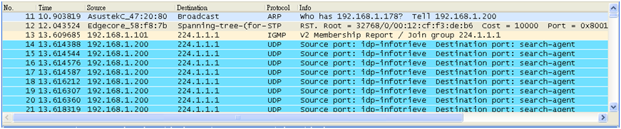
Multicast router sends out Generic Query to solicit the receiver to send report periodically and in this way, the mrouter port and multicast group registration entries will be updated constantly.
Click “product selector tool”
to help you to find what you need.