
SUPPORT AND SERVICE Offering On-line Pre-and-Post Service and Support
FAQ
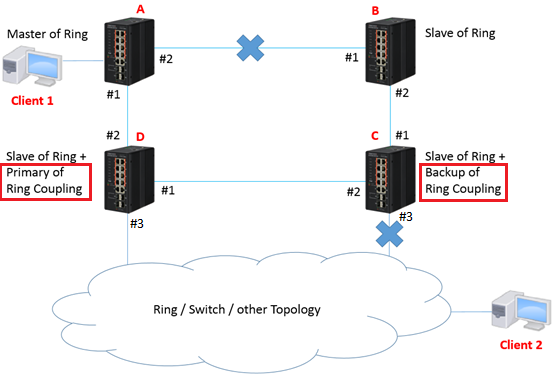
ECIS4500 series support E-Ring – How to configure E-Ring (Coupling)?
The network topology and configuration show as below.
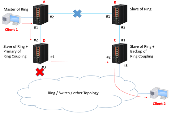
Coupling topology:
Caution:
Please do not connect the Ethernet cable before finishing configuration of Coupling.
Configuration:
1. Since ring protection is a media redundancy protocol (IEC 62439-2), please disable any other anti-loop protection.
1-1 Disable Spanning-Tree on all ports: (It’s enabled by default)

1-2 Disable Loop Protection on all ports: (It’s disabled by default)

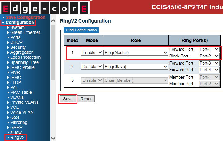
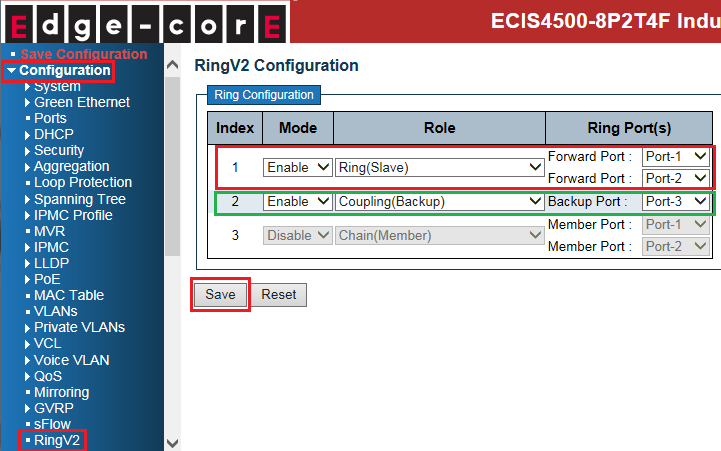
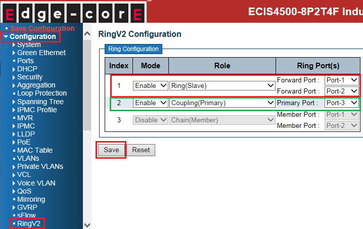
2. Configure Coupling on all switches.
- Master of Ring (switch A):
- Slave of Ring (switch B):

- Slave of Ring + Backup of Ring Coupling (switch C):
- Slave of Ring + Primary of Ring Coupling (switch D):
Caution:
There are 2 types of Coupling ring port:
- Primary port: primary path of ring coupling.
- Backup port: backup path of ring coupling
3. Connect Ethernet cables.
Caution: backup port of coupling switch always blocked by default. ( no link failure)
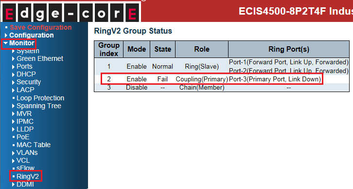
4. Check the Coupling status:
- Master of Ring (switch A):

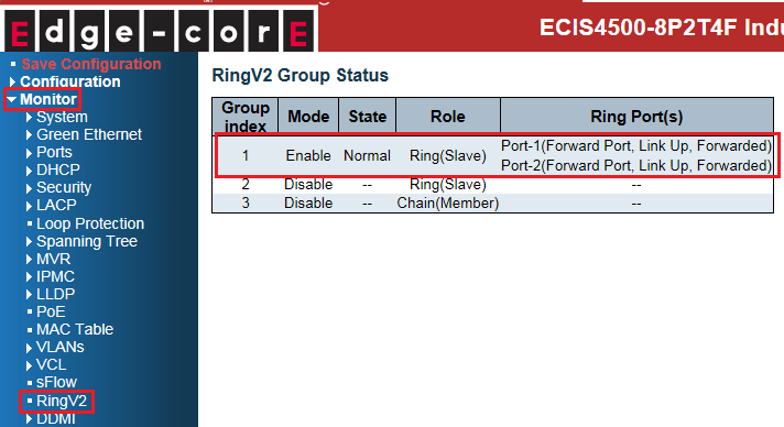
- Slave of Ring (switch B):
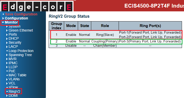
- Slave of Ring + Backup of Ring Coupling (switch C):

- Slave of Ring + Primary of Ring Coupling (switch D):
The status on each switch when link fails:
- Master of Ring (switch A): No impact on switch A.

- Slave of Ring (switch B): No impact on switch B.

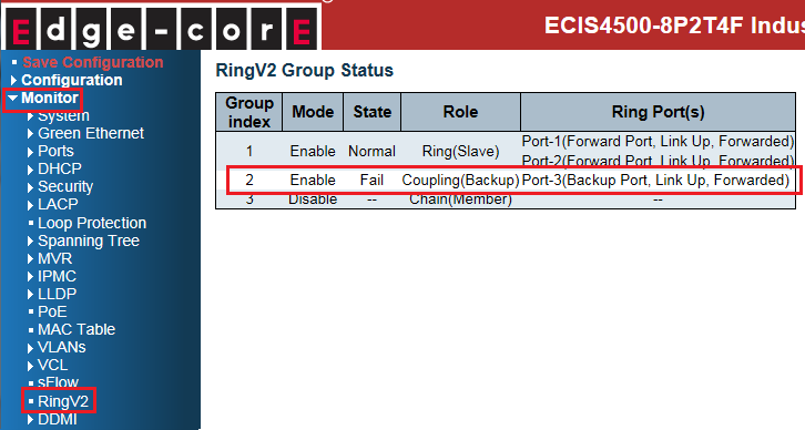
- Slave of Ring + Backup of Ring Coupling (switch C):
The state of port 3 is changed from blocking to forwarding.
- Slave of Ring + Primary of Ring Coupling (switch D): Port 3 link down.
The network topology and configuration show as below.
Coupling topology:
Caution:
Please do not connect the Ethernet cable before finishing configuration of Coupling.
Configuration:
1. Since ring protection is a media redundancy protocol (IEC 62439-2), please disable any other anti-loop protection.
1-1 Disable Spanning-Tree on all ports: (It’s enabled by default)
1-2 Disable Loop Protection on all ports: (It’s disabled by default)
2. Configure Coupling on all switches.
- Master of Ring (switch A):
- Slave of Ring (switch B):
- Slave of Ring + Backup of Ring Coupling (switch C):
- Slave of Ring + Primary of Ring Coupling (switch D):
Caution:
There are 2 types of Coupling ring port:
- Primary port: primary path of ring coupling.
- Backup port: backup path of ring coupling
3. Connect Ethernet cables.
Caution: backup port of coupling switch always blocked by default. ( no link failure)
4. Check the Coupling status:
- Master of Ring (switch A):
- Slave of Ring (switch B):
- Slave of Ring + Backup of Ring Coupling (switch C):
- Slave of Ring + Primary of Ring Coupling (switch D):
The status on each switch when link fails:
- Master of Ring (switch A): No impact on switch A.
- Slave of Ring (switch B): No impact on switch B.
- Slave of Ring + Backup of Ring Coupling (switch C):
The state of port 3 is changed from blocking to forwarding.
- Slave of Ring + Primary of Ring Coupling (switch D): Port 3 link down.
How to configure VLAN mirroring on ECIS4500 series?
Scenario:
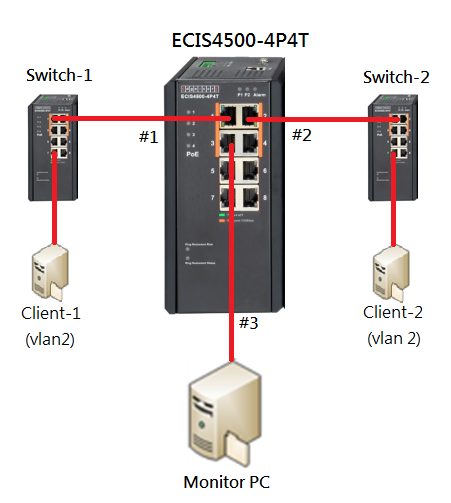
Purpose:
We want to monitor VLAN 2 traffic, which send from Client-1 to Client-2.
By using VLAN mirroring, we are able to capture VLAN 2 traffic on the Monitor PC.
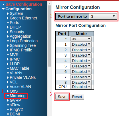
Procedures:
Step 1. Configure Mirroring, then select 3 in “Port to mirror to” column
(The monitor PC is connecting to Port 3)
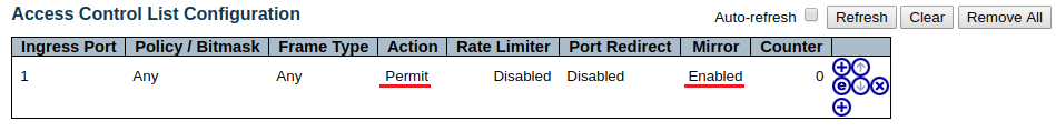
Step 2. Use “Access Control List” to specify the VLAN ID and assign ingress port 1 to monitor VLAN 2 traffic, which send from Client-1 to Client-2.
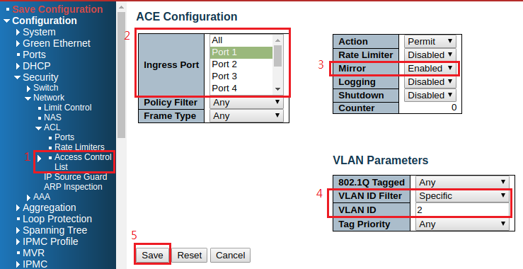
After saving, you can find the ACL as below:
Result:
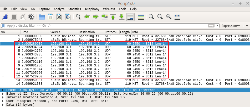
1. Monitor PC will receive the packets, which send from Client-1 to Client-2.
Scenario:
Purpose:
We want to monitor VLAN 2 traffic, which send from Client-1 to Client-2.
By using VLAN mirroring, we are able to capture VLAN 2 traffic on the Monitor PC.
Procedures:
Step 1. Configure Mirroring, then select 3 in “Port to mirror to” column
(The monitor PC is connecting to Port 3)
Step 2. Use “Access Control List” to specify the VLAN ID and assign ingress port 1 to monitor VLAN 2 traffic, which send from Client-1 to Client-2.
After saving, you can find the ACL as below:
Result:
1. Monitor PC will receive the packets, which send from Client-1 to Client-2.
ECIS4500 series support E-Ring – How to configure E-Ring (Dual Homing)?
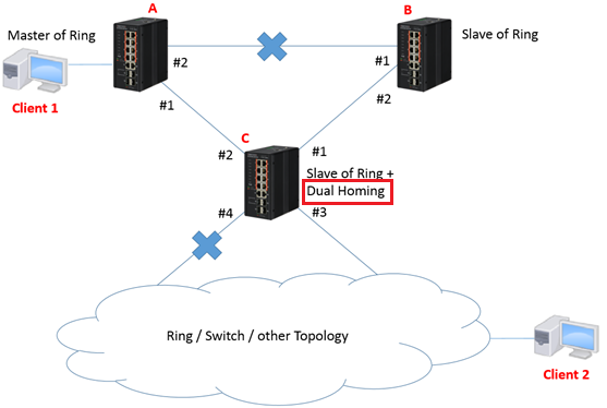
The network topology and configuration show as below.
Dual Homing topology:
Caution:
Please do not connect the Ethernet cable before finishing configuration of Dual Homing.
Configuration:
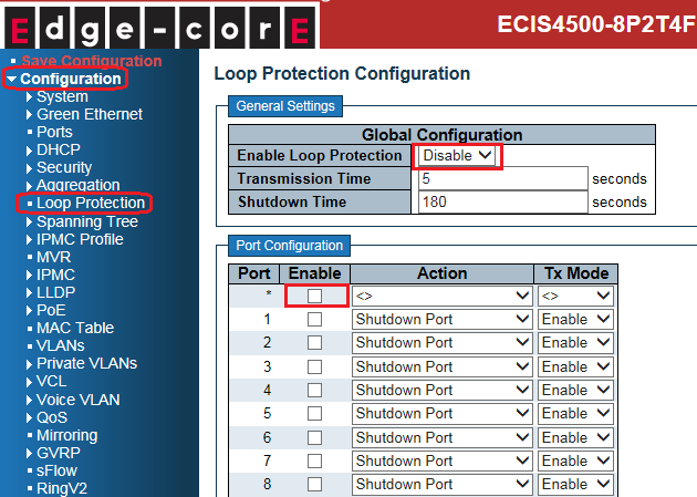
1. Since ring protection is a media redundancy protocol (IEC 62439-2), please disable any other anti-loop protection.
1-1 Disable Spanning-Tree on all ports: (It’s enabled by default)

1-2 Disable Loop Protection on all ports: (It’s disabled by default)
2. Configure Dual Homing on all switches.
- Master of Ring (switch A):

- Slave of Ring (switch B):
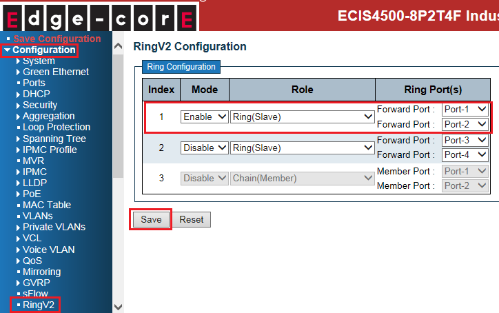
- Slave of Ring + Dual Homing (switch C):
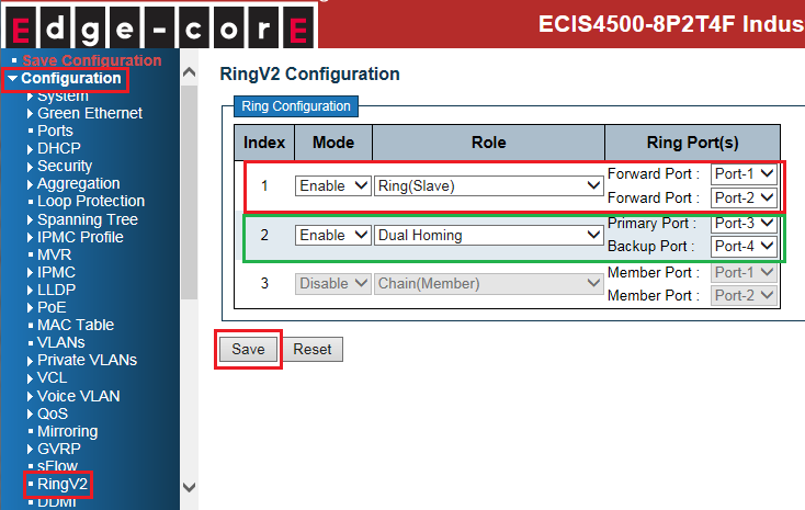
Caution:
There are 2 types of Dual Homing ring port:
- Primary port: primary path of Dual Homing.
- Backup port: backup path of Dual Homing.
Both of them are on the same switch.
3. Connect Ethernet cables.
Caution: backup port of dual homing switch always blocked by default. ( no link failure)
4. Check the Dual Homing status:
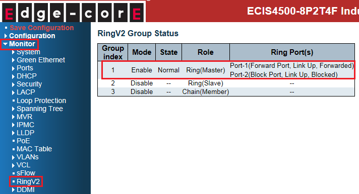
- Master of Ring (switch A):
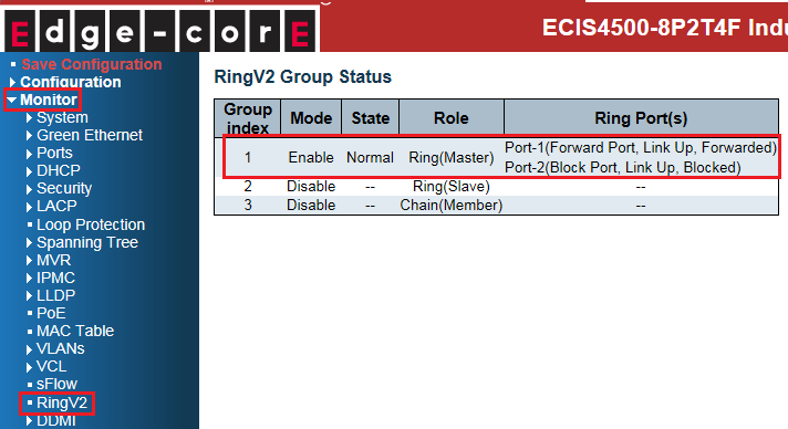
- Slave of Ring (switch B):

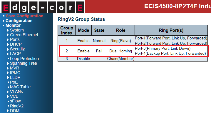
- Slave of Ring + Dual Homing (switch C):
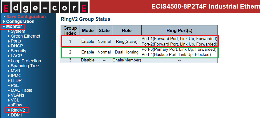
The status on each switch when link fails:
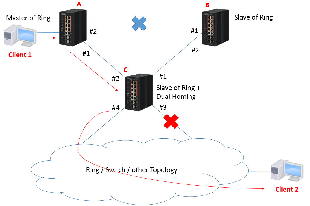
- Master of Ring (switch A): No impact on switch A.
- Slave of Ring (switch B): No impact on switch B.

- Slave of Ring + Dual Homing (switch C):
Port 3 link down.
And the state of port 4 is changed from blocking to forwarding.
The network topology and configuration show as below.
Dual Homing topology:
Caution:
Please do not connect the Ethernet cable before finishing configuration of Dual Homing.
Configuration:
1. Since ring protection is a media redundancy protocol (IEC 62439-2), please disable any other anti-loop protection.
1-1 Disable Spanning-Tree on all ports: (It’s enabled by default)
1-2 Disable Loop Protection on all ports: (It’s disabled by default)
2. Configure Dual Homing on all switches.
- Master of Ring (switch A):
- Slave of Ring (switch B):
- Slave of Ring + Dual Homing (switch C):
Caution:
There are 2 types of Dual Homing ring port:
- Primary port: primary path of Dual Homing.
- Backup port: backup path of Dual Homing.
Both of them are on the same switch.
3. Connect Ethernet cables.
Caution: backup port of dual homing switch always blocked by default. ( no link failure)
4. Check the Dual Homing status:
- Master of Ring (switch A):
- Slave of Ring (switch B):
- Slave of Ring + Dual Homing (switch C):
The status on each switch when link fails:
- Master of Ring (switch A): No impact on switch A.
- Slave of Ring (switch B): No impact on switch B.
- Slave of Ring + Dual Homing (switch C):
Port 3 link down.
And the state of port 4 is changed from blocking to forwarding.
ECIS4500 series support E-Ring – How to configure E-Ring (chain)?
The network topology and configuration show as below,
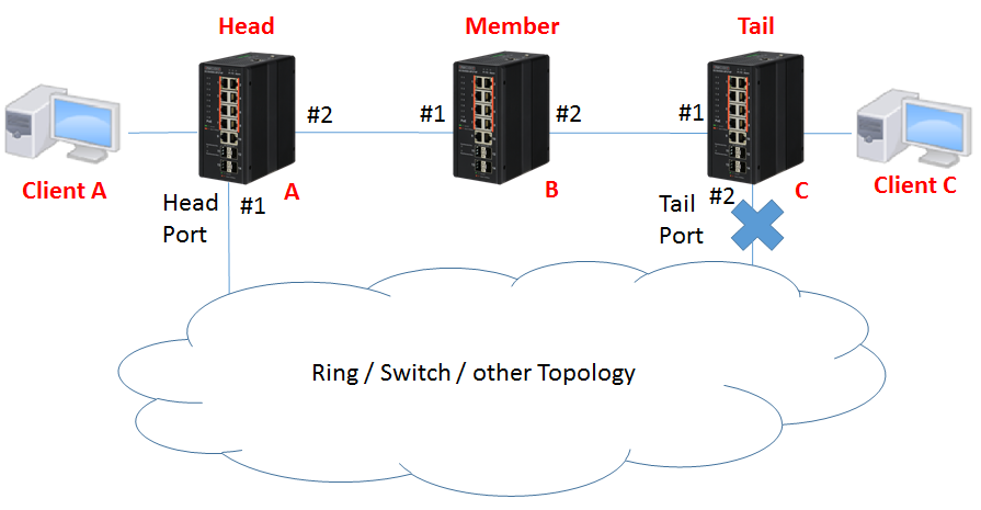
Chain topology:
Caution: Please do not connect the Ethernet cable before finishing configuration of chain.
Note:
There are 3 roles of chain:
- Head: A head switch of the chain.
- Tail: A tail switch of the chain.
- Member: The other switches join the chain topology.
Configuration:
1. Since ring protection is a media redundancy protocol (IEC 62439-2), please disable any other anti-loop protection.
1-1 Disable Spanning-Tree on all ports: (It’s enabled by default)

1-2 Disable Loop Protection on all ports: (It’s disabled by default)

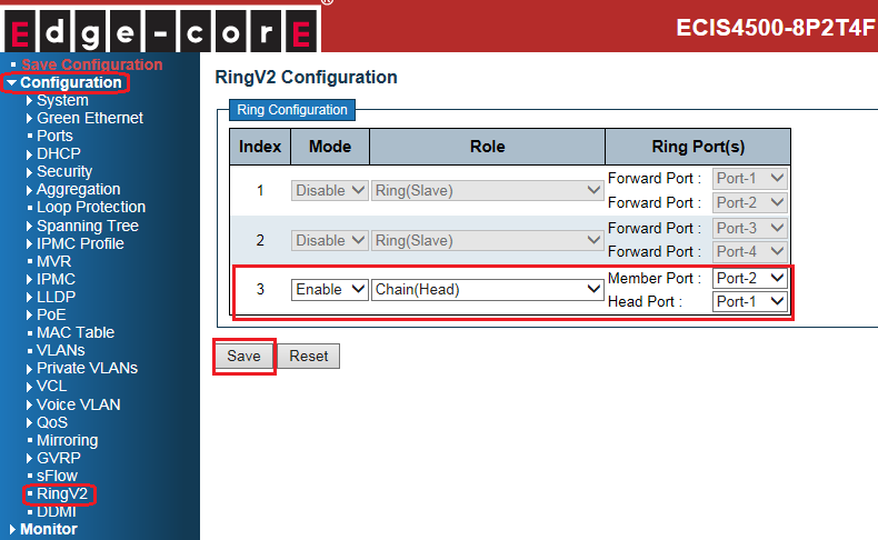
2. Before configuring chain, disable Ring index 1 and index 2
Then configure chain on all switches.
- Head (switch A):
- Member (switch B):

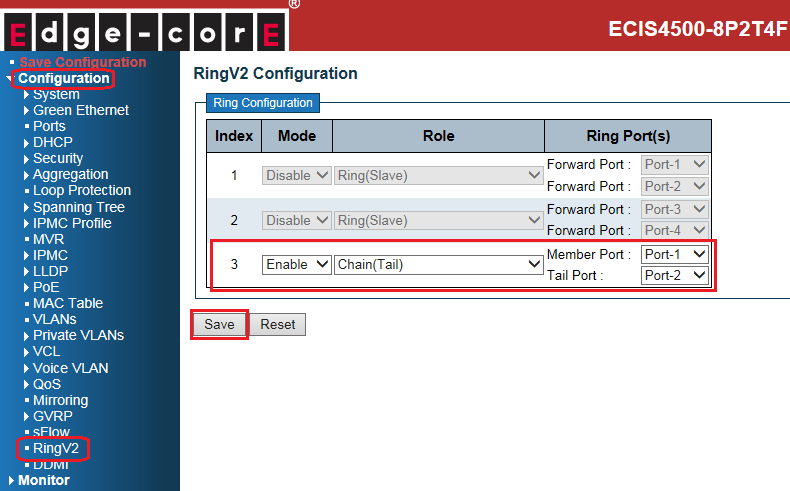
- Tail (switch C):
Caution:
There are 3 types of ring port:
- Head Port: a ring port in head of chain switch that connects to another topology
- Tail Port: a ring port in tail of chain switch that connects to another topology
- Member port: the other ring ports participate in the chain topology.
3. Connect Ethernet cables.
Caution: tail port of tail switch is always blocked by default (no link failure)
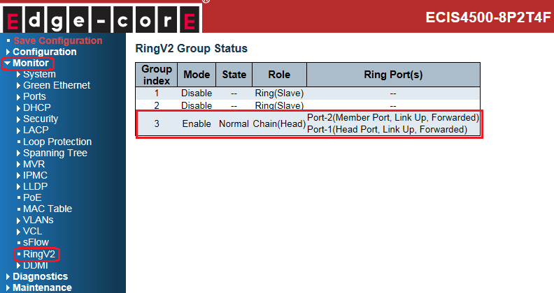
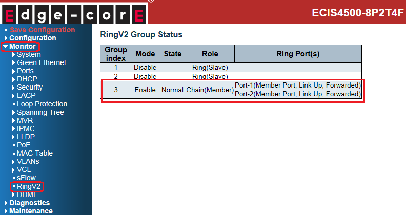
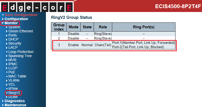
4. Check the chain status:
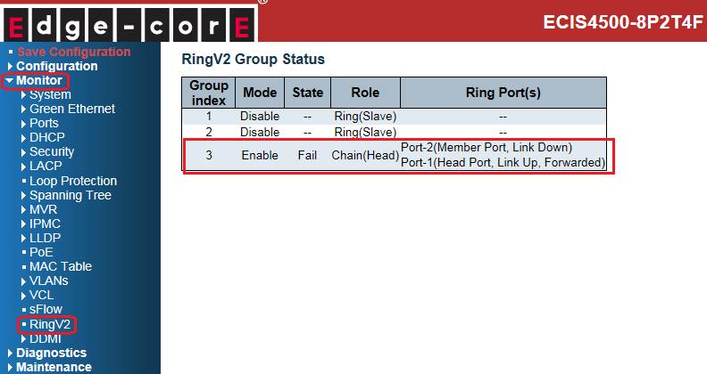
- Head (switch A):
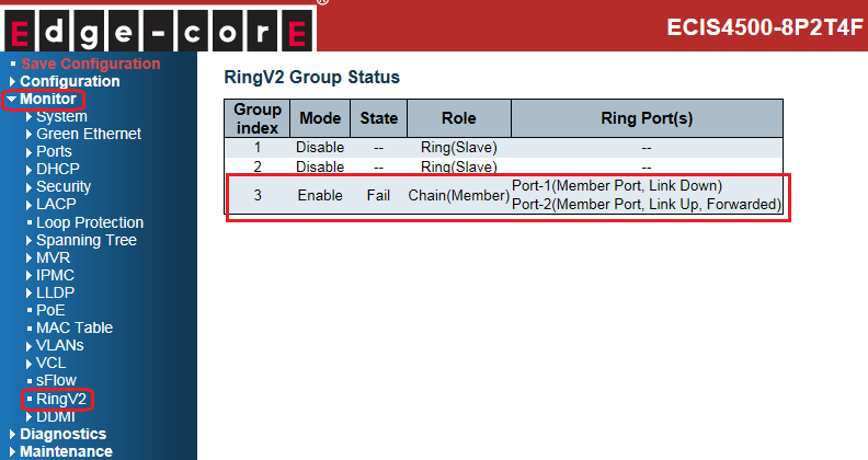
- Member (switch B):
- Tail (switch C):
The status on each switch when link fails:
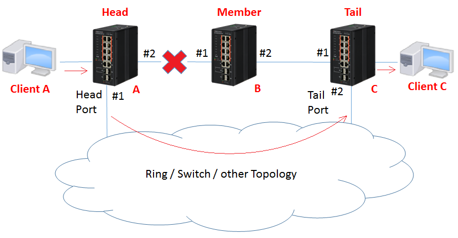
- Head (switch A): port 2 links down.
- Member (switch B): port 1 links down.
- Tail (switch C): state of port 2 is changed from blocking to forwarding.
The network topology and configuration show as below,
Chain topology:
Caution: Please do not connect the Ethernet cable before finishing configuration of chain.
Note:
There are 3 roles of chain:
- Head: A head switch of the chain.
- Tail: A tail switch of the chain.
- Member: The other switches join the chain topology.
Configuration:
1. Since ring protection is a media redundancy protocol (IEC 62439-2), please disable any other anti-loop protection.
1-1 Disable Spanning-Tree on all ports: (It’s enabled by default)
1-2 Disable Loop Protection on all ports: (It’s disabled by default)
2. Before configuring chain, disable Ring index 1 and index 2
Then configure chain on all switches.
- Head (switch A):
- Member (switch B):
- Tail (switch C):
Caution:
There are 3 types of ring port:
- Head Port: a ring port in head of chain switch that connects to another topology
- Tail Port: a ring port in tail of chain switch that connects to another topology
- Member port: the other ring ports participate in the chain topology.
3. Connect Ethernet cables.
Caution: tail port of tail switch is always blocked by default (no link failure)
4. Check the chain status:
- Head (switch A):
- Member (switch B):
- Tail (switch C):
The status on each switch when link fails:
- Head (switch A): port 2 links down.
- Member (switch B): port 1 links down.
- Tail (switch C): state of port 2 is changed from blocking to forwarding.
ECIS4500 series support E-Ring – How to configure E-Ring (balancing chain)?
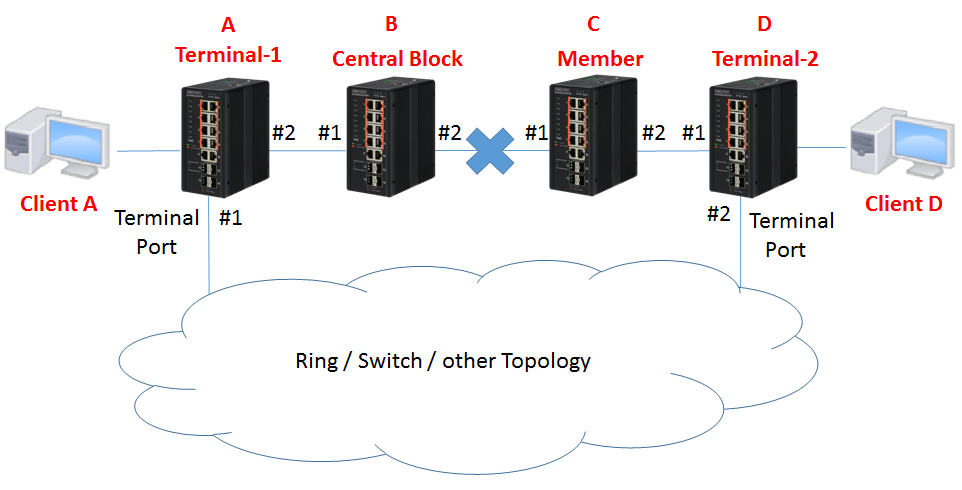
The network topology and configuration show as below,
Balancing chain topology:
Caution: Please do not connect the Ethernet cable before finishing configuration of balancing chain.
Note:
There are 4 roles of balancing chain:
- Terminal-1 / Terminal-2: The Switch connect to other topology.
- Central Block: The Switch has a central block port
- Member: The other switches joined balancing chain topology
Configuration:
1. Since ring protection is a media redundancy protocol (IEC 62439-2), please disable any other anti-loop protection.
1-1 Disable Spanning-Tree on all ports: (It’s enabled by default)
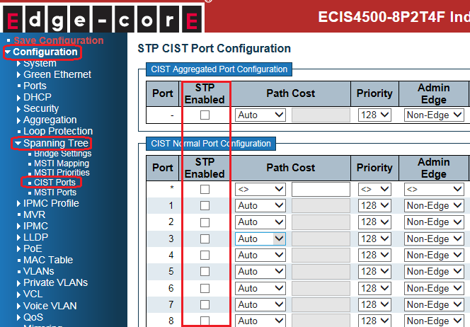
1-2 Disable Loop Protection on all ports: (It’s disabled by default)

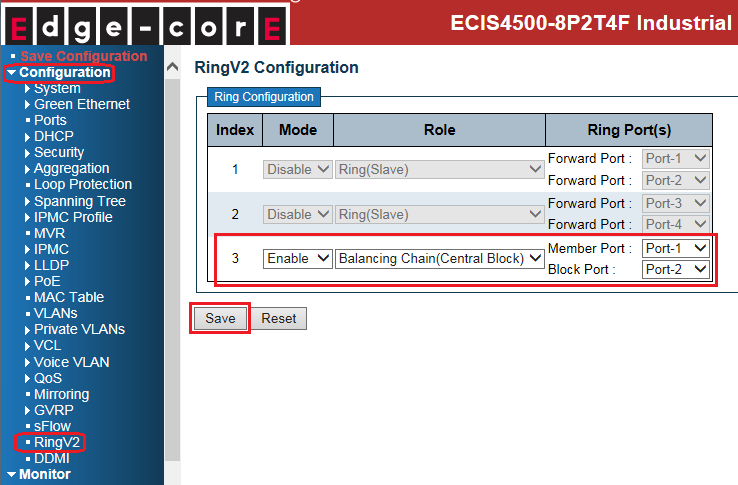
2. Before configuring balancing chain, disable Ring index 1 and index 2
Then configure balancing chain on all switches.
- Terminal-1(switch A):

- Central Block (switch B):
- Member (switch C):

- Terminal-2(switch D):
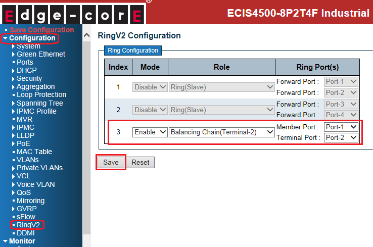
Caution:
There are 3 types of ring port:
- Terminal Port: ring ports connect between chain & other segments
- Central Block Port: a ring port in the central block of balancing chain
- Member port: the other ring port join balancing chain topology
3. Connect Ethernet cables.
Caution: central block port of central block switch always blocked by default. (no link failure)
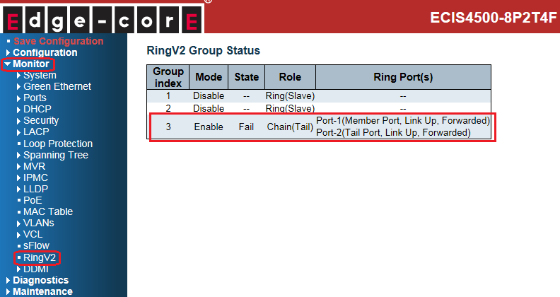
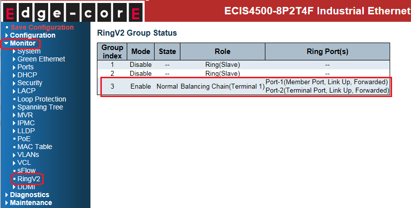
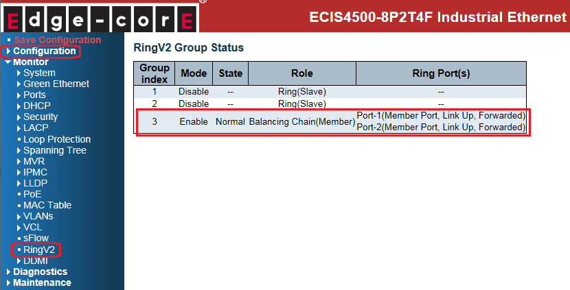
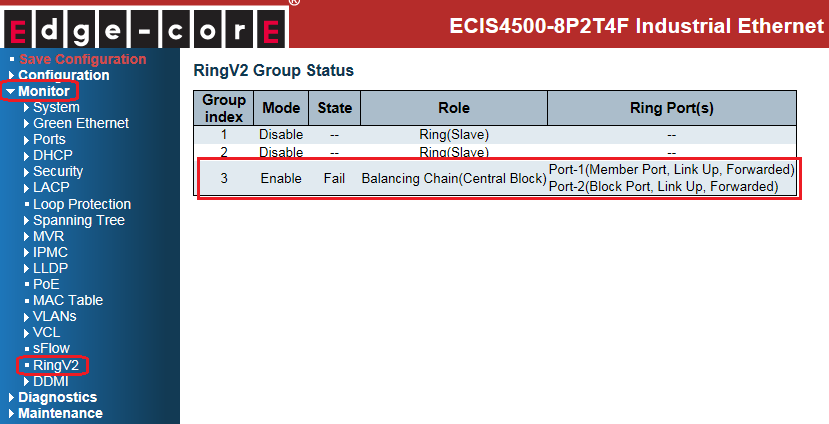
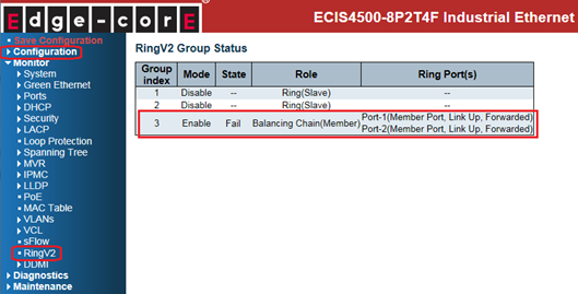
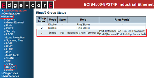
4. Check the balancing chain status:
- Terminal-1(switch A):
- Central Block (switch B):

- Member (switch C):
- Terminal-2(switch D):

The status on each switch when link failed:
- Terminal-1(switch A): port 1 links down.

- Central Block (switch B): state of port 2 is changed from blocking to forwarding.
- Member (switch C): member ports still keep forwarding.
- Terminal-2(switch D): member ports still stay in forwarded.
The network topology and configuration show as below,
Balancing chain topology:
Caution: Please do not connect the Ethernet cable before finishing configuration of balancing chain.
Note:
There are 4 roles of balancing chain:
- Terminal-1 / Terminal-2: The Switch connect to other topology.
- Central Block: The Switch has a central block port
- Member: The other switches joined balancing chain topology
Configuration:
1. Since ring protection is a media redundancy protocol (IEC 62439-2), please disable any other anti-loop protection.
1-1 Disable Spanning-Tree on all ports: (It’s enabled by default)
1-2 Disable Loop Protection on all ports: (It’s disabled by default)
2. Before configuring balancing chain, disable Ring index 1 and index 2
Then configure balancing chain on all switches.
- Terminal-1(switch A):
- Central Block (switch B):
- Member (switch C):
- Terminal-2(switch D):
Caution:
There are 3 types of ring port:
- Terminal Port: ring ports connect between chain & other segments
- Central Block Port: a ring port in the central block of balancing chain
- Member port: the other ring port join balancing chain topology
3. Connect Ethernet cables.
Caution: central block port of central block switch always blocked by default. (no link failure)
4. Check the balancing chain status:
- Terminal-1(switch A):
- Central Block (switch B):
- Member (switch C):
- Terminal-2(switch D):
The status on each switch when link failed:
- Terminal-1(switch A): port 1 links down.
- Central Block (switch B): state of port 2 is changed from blocking to forwarding.
- Member (switch C): member ports still keep forwarding.
- Terminal-2(switch D): member ports still stay in forwarded.
How to configure MAC Based VLAN, IP Subnet Based VLAN, Protocol Based VLAN on ECIS4500 series?
- 1. MAC Based VLAN
Assign VLAN to interface base on client’s MAC address.
Scenario:
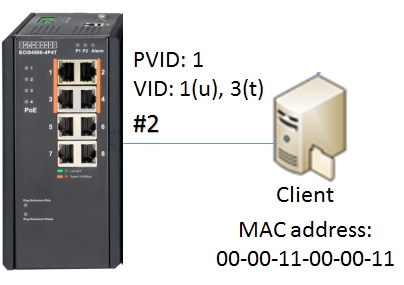
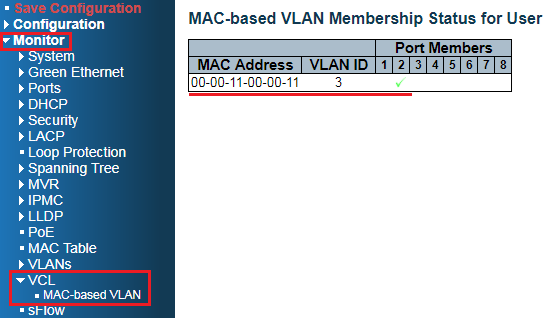
Client with MAC address 00-00-11-00-00-11, is assigned to VLAN 3.
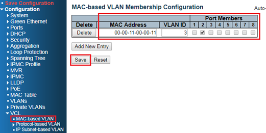
Configuration steps:
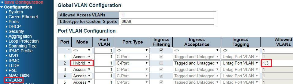
1. Specific the MAC address of client to the VLAN 3(on port 2).
2. Allow VLAN 3 on port 2. (PVID:1 VID:1u,3t)
Result:
Check MAC-Based VLAN table.
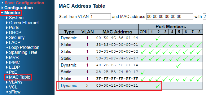
Also, this MAC address is learned on VLAN3 in the MAC table if the switch receives packets from client.
- 2. IP Subnet Based VLAN
Assign VLAN to interface base on client’s IP address/IP subnet.
Scenario:
Clients belong to IP subnet 192.168.4.0/24, are assigned to VLAN 4.
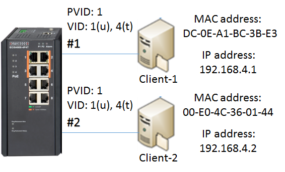
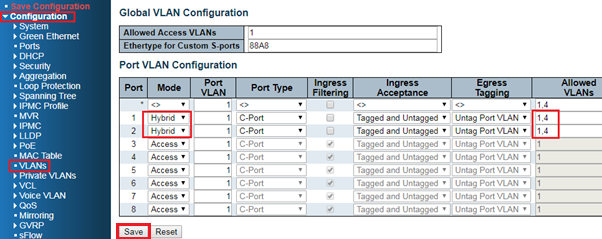
Configuration Steps:
1. Assign IP subnet 192.168.4.0/24 to the VLAN 4(on port 1 and 2).
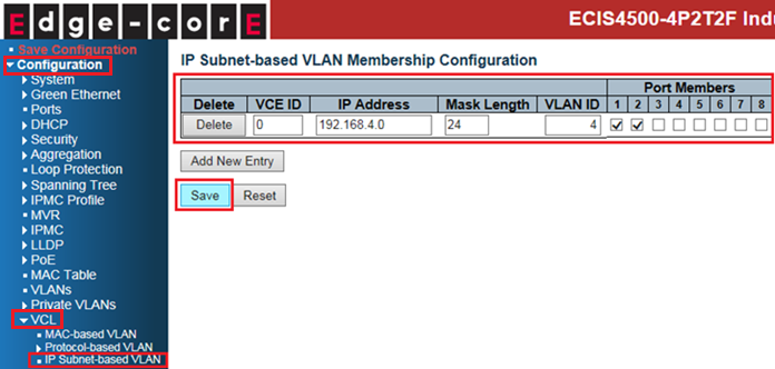
2. Allow VLAN 4 on port 1 and 2. (PVID:1 VID:1u,4t)
3. Add static ARP entry for client-1 and client-2 by manual on PC.
(since ARP packet without IP header does not belong to IP packet)
For example, in Windows OS:
arp –s “IP address” “MAC address”

OR
netsh interface ip add neighbors “name of NIC” “IP address” “MAC address”

Command: arp –a to check the ARP table.
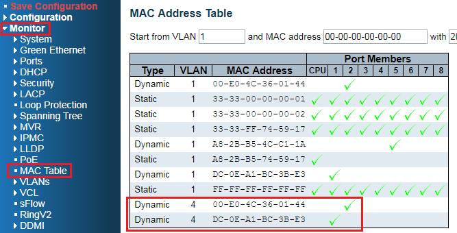
Result:
Clients belong to IP subnet 192.168.4.0/24, are assigned to VLAN 4.
Also, these MAC addresses of clients are learnedt on VLAN4 in the MAC table.
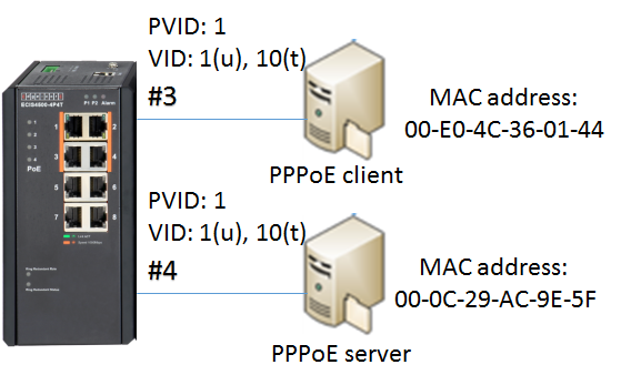
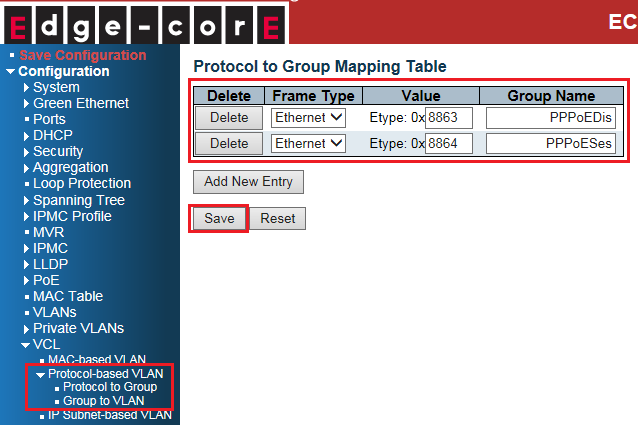
- 3. Protocol Based VLAN
Assign VLAN to interface base on its protocol.
Scenario:
Protocol PPPoE (0x8863 and 0x8864) are assigned to VLAN 10.
Configuration Steps:
1. Protocol groups
Create protocol groups PPPoE_Discovery(0x8863) and PPP_Session(0x8864).
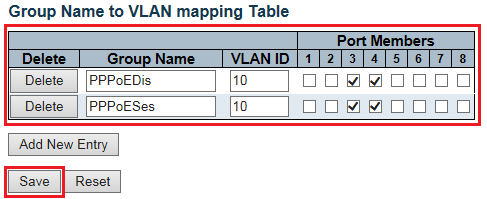
2. Assign protocol groups to VLAN
Mapping the groups to VLAN 10(on port 3 and 4).
3. Allow VLAN 10 on port 3 and 4. (PVID:1 VID:1u,10t)
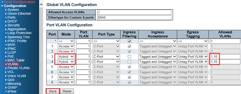
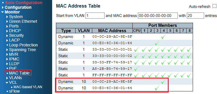
Result:
PPPoE client/server on port 3 and 4 are assigned to the VLAN 10.
- 1. MAC Based VLAN
Assign VLAN to interface base on client’s MAC address.
Scenario:
Client with MAC address 00-00-11-00-00-11, is assigned to VLAN 3.
Configuration steps:
1. Specific the MAC address of client to the VLAN 3(on port 2).
2. Allow VLAN 3 on port 2. (PVID:1 VID:1u,3t)
Result:
Check MAC-Based VLAN table.
Also, this MAC address is learned on VLAN3 in the MAC table if the switch receives packets from client.
- 2. IP Subnet Based VLAN
Assign VLAN to interface base on client’s IP address/IP subnet.
Scenario:
Clients belong to IP subnet 192.168.4.0/24, are assigned to VLAN 4.
Configuration Steps:
1. Assign IP subnet 192.168.4.0/24 to the VLAN 4(on port 1 and 2).
2. Allow VLAN 4 on port 1 and 2. (PVID:1 VID:1u,4t)
3. Add static ARP entry for client-1 and client-2 by manual on PC.
(since ARP packet without IP header does not belong to IP packet)
For example, in Windows OS:
arp –s “IP address” “MAC address”
OR
netsh interface ip add neighbors “name of NIC” “IP address” “MAC address”
Command: arp –a to check the ARP table.
Result:
Clients belong to IP subnet 192.168.4.0/24, are assigned to VLAN 4.
Also, these MAC addresses of clients are learned
- 3. Protocol Based VLAN
Assign VLAN to interface base on its protocol.
Scenario:
Protocol PPPoE (0x8863 and 0x8864) are assigned to VLAN 10.
Configuration Steps:
1. Protocol groups
Create protocol groups PPPoE_Discovery(0x8863) and PPP_Session(0x8864).
2. Assign protocol groups to VLAN
Mapping the groups to VLAN 10(on port 3 and 4).
3. Allow VLAN 10 on port 3 and 4. (PVID:1 VID:1u,10t)
Result:
PPPoE client/server on port 3 and 4 are assigned to the VLAN 10.
ECIS4500 series support E-Ring – How to configure E-Ring(single ring)?
The introduction of the behavior of E-Ring when there is a link failure
The ECIS4500 series support fast failover ring protection (E-Ring) with the ability for the network to detect and recover from incidents without impacting users, meeting the most demanding quality and availability requirements. Rapid recovery time when problems do occur is as low as 20 ms.
How to configure E-Ring(single ring)?
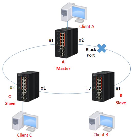
The network topology and configuration show as below,
Single ring topology:
※Please do not connect the Ethernet cable before finishing configuration of E-ring.
Configuration:
1. Since ring protection is a media redundancy protocol (IEC 62439-2), please disable any other anti-loop protection.
1-1 Disable Spanning-Tree on all ports: (Spanning-Tree by default is enabled)

1-2 Disable Loop Protection on all ports: (Loop Protection by default is disabled)

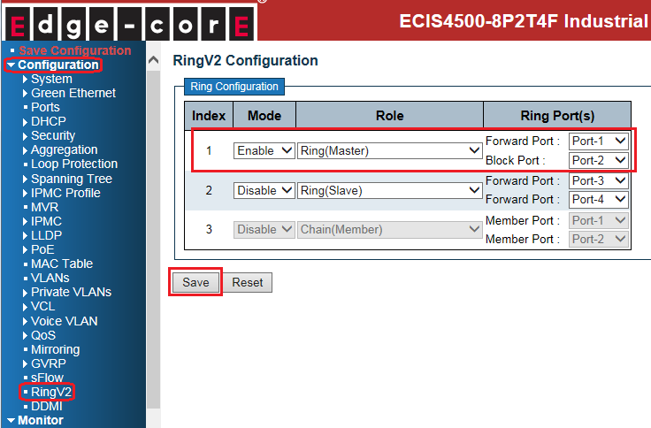
2. Configure E-ring on all switches.
- Master(switch A):
- Slave(switch B, C):
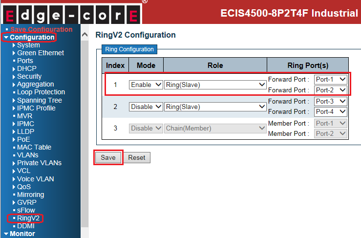
※There is only one Master in the ring topology, others are Slaves.
3. Connect Ethernet cables.
※Block port is always on the Master device by default. (If there is no link failure happened)
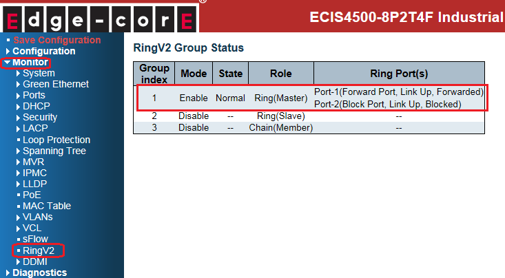
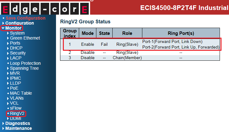
4. Check the E-ring status:
- Master(switch A):
- Slaves(switch B, C):

Introduction: The behavior of E-Ring if link failure:
If state of E-ring is normal, the blocking port is on the Master device (switch A).

Then, the data traffic from Client A to Client B will be forwarded through switch A -> switch C -> switch B.
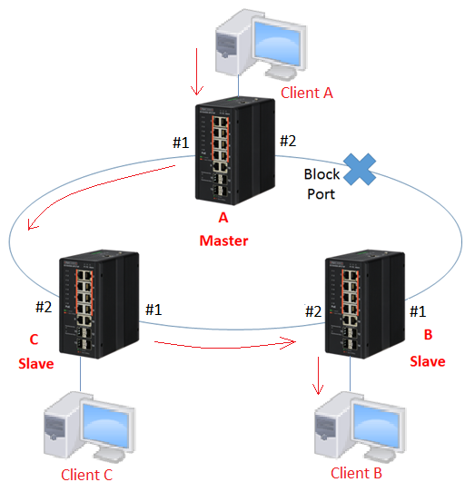
If there is a link failure happened as below, the blocking port will change the state from blocking to forwarding within 20ms. Also, the state of E-ring will change to “Fail”. Then the traffic flow will change to switch A -> switch B
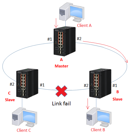
The status on each switch when link failure:
- Master(switch A): state of port 2 is changed from blocking to forwarding.

- Slave(switch B): port 2 links down.

- Slave(switch C): port 1 links down.
The introduction of the behavior of E-Ring when there is a link failure
The ECIS4500 series support fast failover ring protection (E-Ring) with the ability for the network to detect and recover from incidents without impacting users, meeting the most demanding quality and availability requirements. Rapid recovery time when problems do occur is as low as 20 ms.
How to configure E-Ring(single ring)?
The network topology and configuration show as below,
Single ring topology:
※Please do not connect the Ethernet cable before finishing configuration of E-ring.
Configuration:
1. Since ring protection is a media redundancy protocol (IEC 62439-2), please disable any other anti-loop protection.
1-1 Disable Spanning-Tree on all ports: (Spanning-Tree by default is enabled)
1-2 Disable Loop Protection on all ports: (Loop Protection by default is disabled)
2. Configure E-ring on all switches.
- Master(switch A):
- Slave(switch B, C):
※There is only one Master in the ring topology, others are Slaves.
3. Connect Ethernet cables.
※Block port is always on the Master device by default. (If there is no link failure happened)
4. Check the E-ring status:
- Master(switch A):
- Slaves(switch B, C):
Introduction: The behavior of E-Ring if link failure:
If state of E-ring is normal, the blocking port is on the Master device (switch A).
Then, the data traffic from Client A to Client B will be forwarded through switch A -> switch C -> switch B.
If there is a link failure happened as below, the blocking port will change the state from blocking to forwarding within 20ms. Also, the state of E-ring will change to “Fail”. Then the traffic flow will change to switch A -> switch B
The status on each switch when link failure:
- Master(switch A): state of port 2 is changed from blocking to forwarding.
- Slave(switch B): port 2 links down.
- Slave(switch C): port 1 links down.
Click “product selector tool”
to help you to find what you need.