
SUPPORT AND SERVICE Offering On-line Pre-and-Post Service and Support
FAQ
What is a "cloud" exactly?
Creating your first Cloud
- If you don't yet have a login to the ecCLOUD , click the "I want to register" link from the login page.
- Fill in your name, email address, and accept the user agreement.
- You should receive a verification email. Click on the link within the email in order to verify your account.
-
Once you are registered as a user on the ecCLOUD , you will be given the option to create a cloud after you first login:

A: No
Q2: If I forget the EC-PP200 IP address, how can I find its IP address?
A: You can print out the EC-PP200 configuration through the following steps:
1. Power off the EC-PP200
2. Press and hold the
 button then power on the EC-PP200 for few seconds and release the holding
3. Check the printed paper to find the IP address
Q3: What should I do if I forget the EC-PP200 password?
A: You don’t need to type in the login name and password to access the printer’s UI
Q4: Why I can’t print out the ticket?
A: You can check several things to verify the issue
1. If the cable is connected properly?
2. Is there a thermal paper in the printer?
3. Does the printer power on?
4. If the printer status is a green light on the controller’s POS printer setting?
5. If the printer connects to the controller via Ethernet cable, does the port number set to 9100 on the controller’s POS printer setting?
Q5: Why the EC-PP200 status is not a green light on the controller’s POS printer setting?
A: Check if the EC-PP200 IP address is the same IP subnet with the controller’s default zone.
Q6: Why the printed paper is blank without any words?
A: Try to let the EC-PP200 prints the words on another side of the paper. There is only one side of the thermal paper can be printed.
Q7: Can I install the EC-PP200 on my computer?
A: No, because there is no installed driver for the computer.
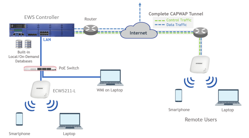
User can deploy this scenario if there RADIUS server is in a intranet, but they could have a Controller deployed with a public IP, so that their network could extend across the Internet, penetrating NATs, and deploy the local network to a remote site, such as penetrating the Great Fire Wall. Please click here to know more.
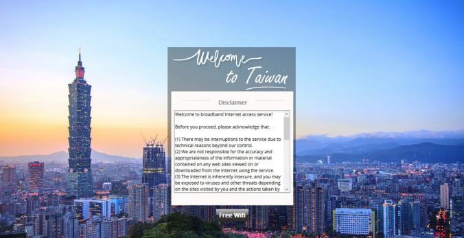
The customizable pages of a Service Zone are divided into two parts: Login Page Customization and Message Page Customization.
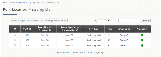
In Login Page Customization, administrators can modify the content within Service Disclaimer, General Login Page, Port Location Mapping Free Login, and Port Location Mapping Paid Access Login.
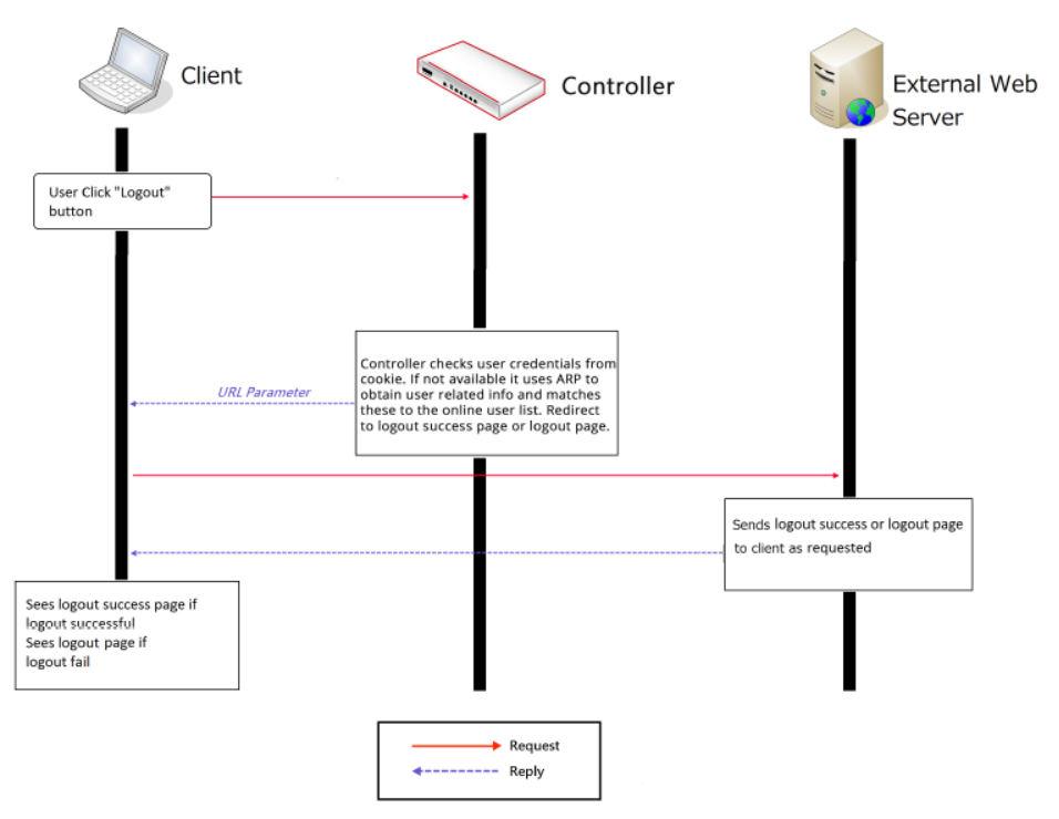
In Message Page Customization, the Login Success Page, Login Succeeded Page. For On-Demand Users, Login Failed Page, Logout Page, Logout Succeeded Page, Logout Failed Page can be customized.
Please click here to know more details.
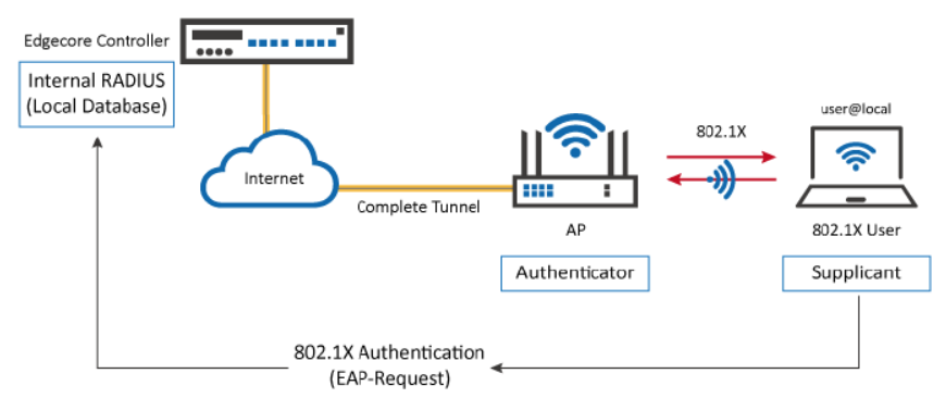
In this technical guide, the authentication flow on the controller is illustrated using a flowchart. With this flowchart, readers would be able to understand the order in which authentication methods are presented on the controller, so they could better plan the authentication methods they'd like to leverage as well as better understand how they could troubleshoot if necessary.
Furthermore, as will be seen from the flowchart, a variety of authentication methods are available on the controller for network access control, including web-based, 802.1X, WISPr and MAC authentication. How each authentication method works and where to configure its settings are also explained.
Please click here to know more details.
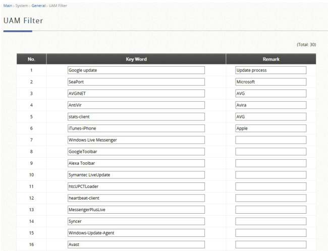
UAM is also one of the authentication methods supported by the EWS controller, besides other authentication methods such as 802.1X authentication and auto login by the controller based on the MAC addresses and/or IP addresses of the devices used. Furthermore, the EWS controller also supports customization to the behavior of UAM through a UAM filter and provides UAMD log. Please click here to know more.
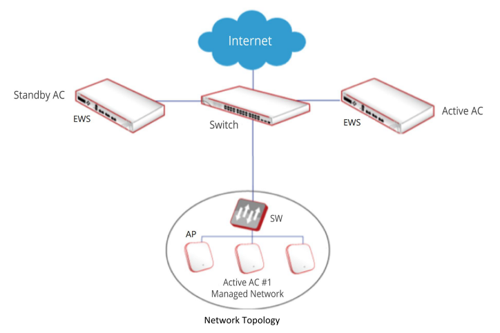
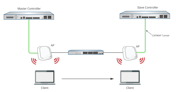
Normally, when a user moves from an edge AP managed by one Controller to another edge AP managed by another Controller, the user would experience network disconnection and have to re-login. However, with Cross Gateway Roaming, the user can stay logged in to the network and continue to enjoy network access without interruption.
Cross Gateway Roaming adopts a star topology that consists of one Master Node that sits at the center and multiple Slave Nodes that connect to it. One Master Node may connect with up to 15 Slave Nodes. A Controller can be in Master Mode or Slave Mode depending on its Cross Gateway Roaming settings.
This technical guide aims to explain the setup flow of Cross Gateway Roaming on the Controller. Below are two exemplary network deployments that deploy Cross Gateway Roaming so that authenticated users could seamlessly roam within the larger network. Please Click here to know more.
Scenario:

Configuration:
1. Set the Wired Network Discovery VLAN ID to 10. Wired Network Discovery VLAN ID is the management VLAN that AP will using to communicate with AC controller after success managed by AC controller.
(When the value not set to zero, means enabled VLAN classification at ALL AP that using this profile)

2. Modify the VLAN at corresponding VAP that want to enabled (default VLAN is 1)


3. Then apply the profile to take effect the configuration. (Remember need configure corresponding VLAN at the switch first before apply the profile.)
Captive Portal Scenario

Setup Captive Portal
1. Enabled Captive Portal at Global Configuration.
System > Security > Captive Portal> Global Configuration

2. Set Verification Mode as Local at CP Configuration.
System > Security > Captive Portal> CP Configuration

3. Add user at Local User.
System > Security > Captive Portal> Local User

4. Add the VAP to Associated Interface at Interface Association page.
System > Security > Captive Portal> Interface Association

Wireless Client
Before Pass the Captive Portal Authentication, then client can!|t access internet.

After Pass the Captive Portal Authentication, then client will be able to access internet.

Scenario:

Fit AP: ECW5110-L
Example: Using Windows 2003 DHCP Server to setup DHCP options 138
Step 1: Right-click and select "Set Predefined Options":

Step 2: Press "Add" button:

Step 3: Create a DHCP option 138 entry as below:

Step 4: Right-click at 'Scope Options', and select "Configure Options":

Step 5: Check DHCP Option 138 and add the AC IP address:


Results:

- SMC
Software Release v1.0.0.x
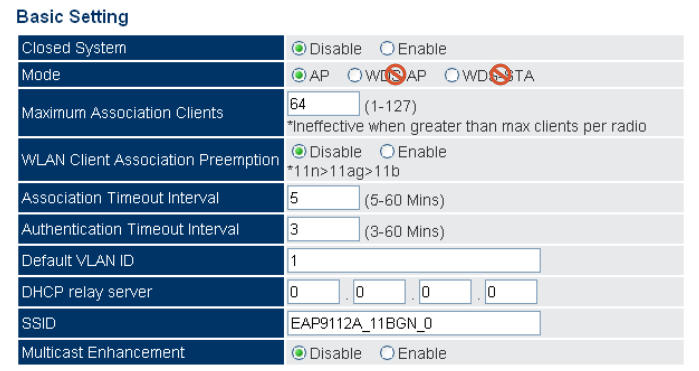
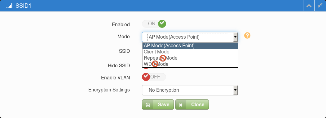
VAP Basic Settings (Default is AP mode.)
SMC2890W-AG, SMC2891W-AG
Software Release v4.3.x.x
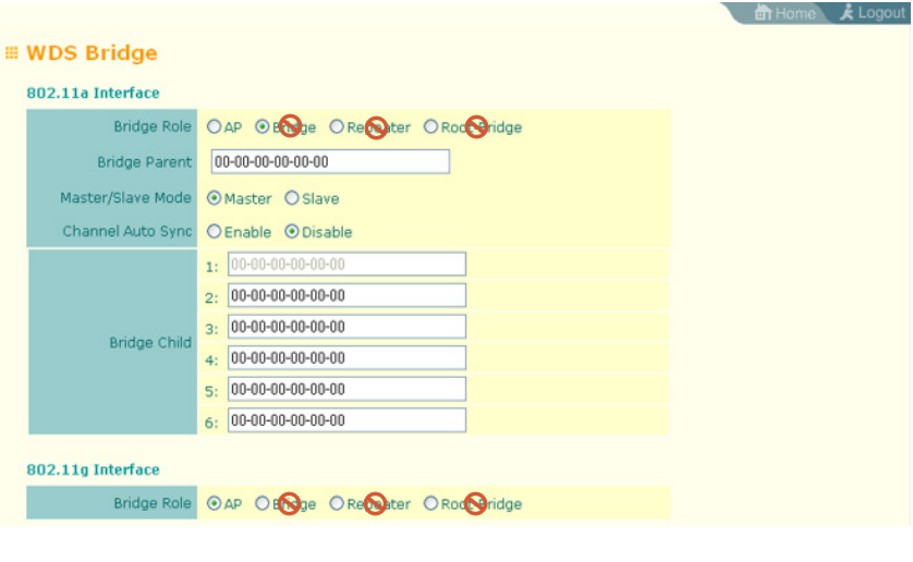
WDS Bridge Settings (Default is AP mode.)
- Edgecore
Software Release v1.0.x.x
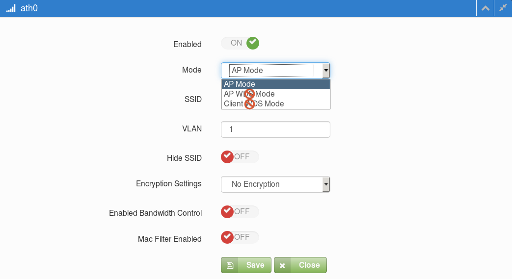
VAP Basic Settings (Default is AP mode.)

ECW5212
Software Release v2.1.1.x
Basic Radio Configuration Dialog Box (Default is AP mode.)
ECW5320, ECWO5320
Software Release V2.0.x.x
Basic Radio Configuration Dialog Box (Default is AP mode.)
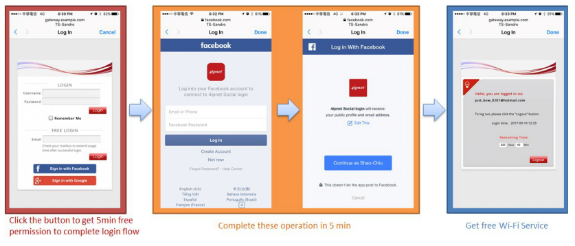
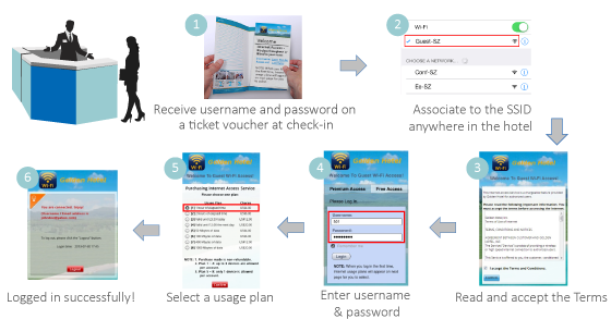
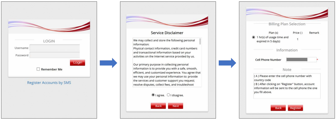
User Login Flow
Typically, the user login flow as below figure
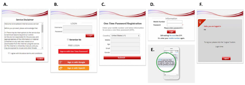
- Service Disclaimer (if enabled): presents the terms and service that have to be agreed for continuing the login process
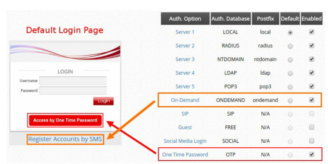
- General Login Page: presents different login options as customized by the administrator
- OTP Registration Page: allows user to enter their mobile number, a pre-configured questionnaire can also be presented for the user to fill out
- Receive SMS with OTP: user receives a OTP via a SMS test message on the mobile phone
- OTP Authentication Page: allows user to enter the OTP for authentication
- Login Success Page: user is authenticated and can start surfing the Internet
- Group: Clients authenticated by OTP will be assigned to this Group for Policy enforcement
- OTP Client Information: Displays information of clients authenticated by OTP (Login Time, Phone number, MAC address, Answers to Questionnaire)
- Delete All: Delete all the entries in OTP Client Information. For example, after downloading the entries, use this function to remove old entries.
- Default Country Code: Default country code to be displayed on the login page
- Length of Mobile Number: Number of digits allowed for mobile number
- Quota (Time Duration): Time duration of Internet access for logged-in clients. The maximum duration is 364 days 23 hours and 59 Minutes.
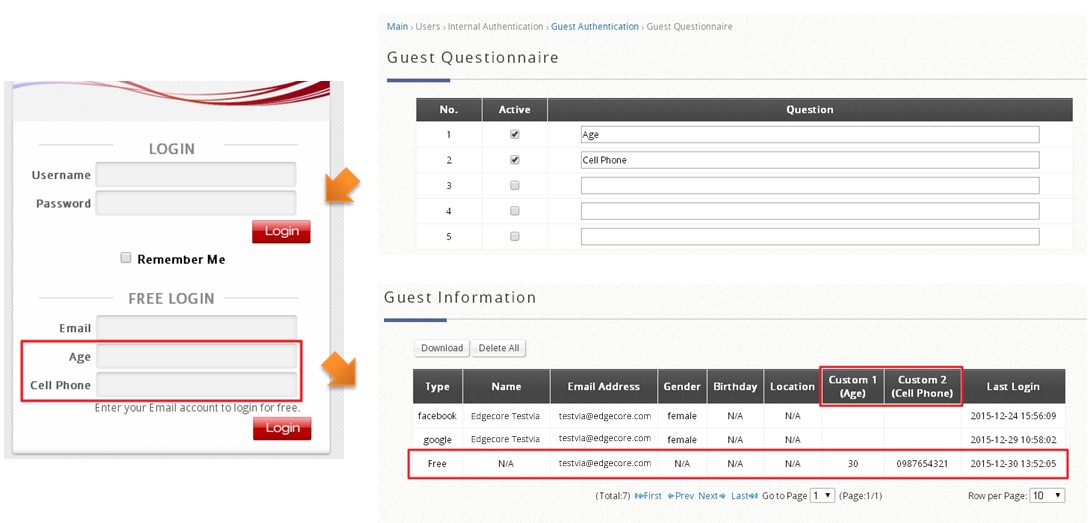
- Questionnaire: A questionnaire with up to 5 questions can be displayed on the Login Page
- SMS Gateway: Integration with third-party SMS gateway services. Integration with Clickatell (Legacy/New) and other service providers (via API) is available
- Web Page Customization: Currently, only the options of Edgecore Default and Customize with Template are supported. Other customization options will become available in the future.
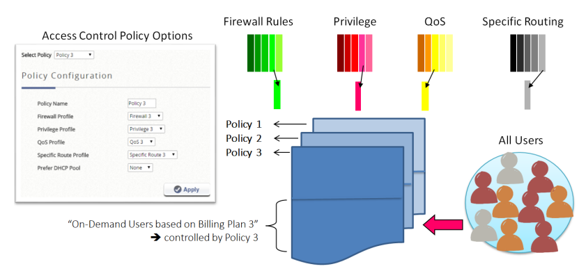
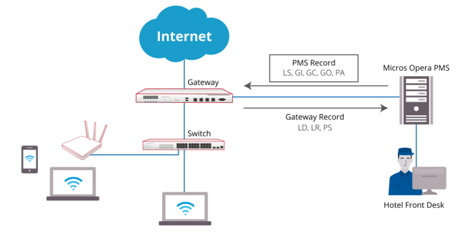
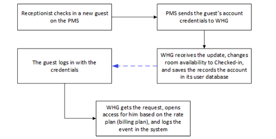
For PMS other than Micros Opera, a table of attributes is provided in this guide for system integrators to achieve integration with the Controller. Implementation examples are also given to help system integrators plan and carry out integration.
With such integration, the following can be achieved
1. Check-in information entered into the PMS by the hotel receptionist can be used as Wi-Fi login credentials
2. Data usage of each logged-in guest can be monitored and managed from the Controller
3. The Controller can send billing plan rate the user chose to the PMS as part of the check-out information
After reading this document, the reader should have a clear understanding of how user data from existing PMS can be used in authenticated Wi-Fi services and how to pragmatically set up the integration on the Controller. Click here to know more details for Third Party PMS Intergration.
In this guide, mechanisms of these different MAC address-based access control options are explained and a comparison between them is given. Possible scenarios for these MAC address-based access control options are also illustrated. Moreover, step-by-step configuration guides are provided to facilitate the configuration process. Click here to know more details.

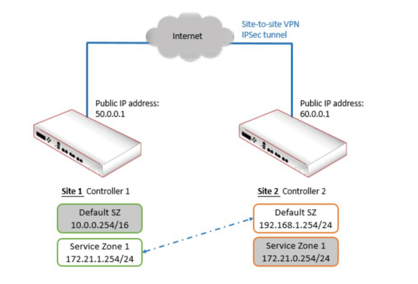
- The Site-to-Site VPN feature on the controller is introduced, and guidance on how to build and configure an exemplary site-to-site VPN is provided through step-by-step explanations. Click here to know more details.
- The Remote VPN feature on the controller is introduced, and guidance on how to setup and configure remote VPNs on the controller as well as on client devices is provided. Click here to know more details.
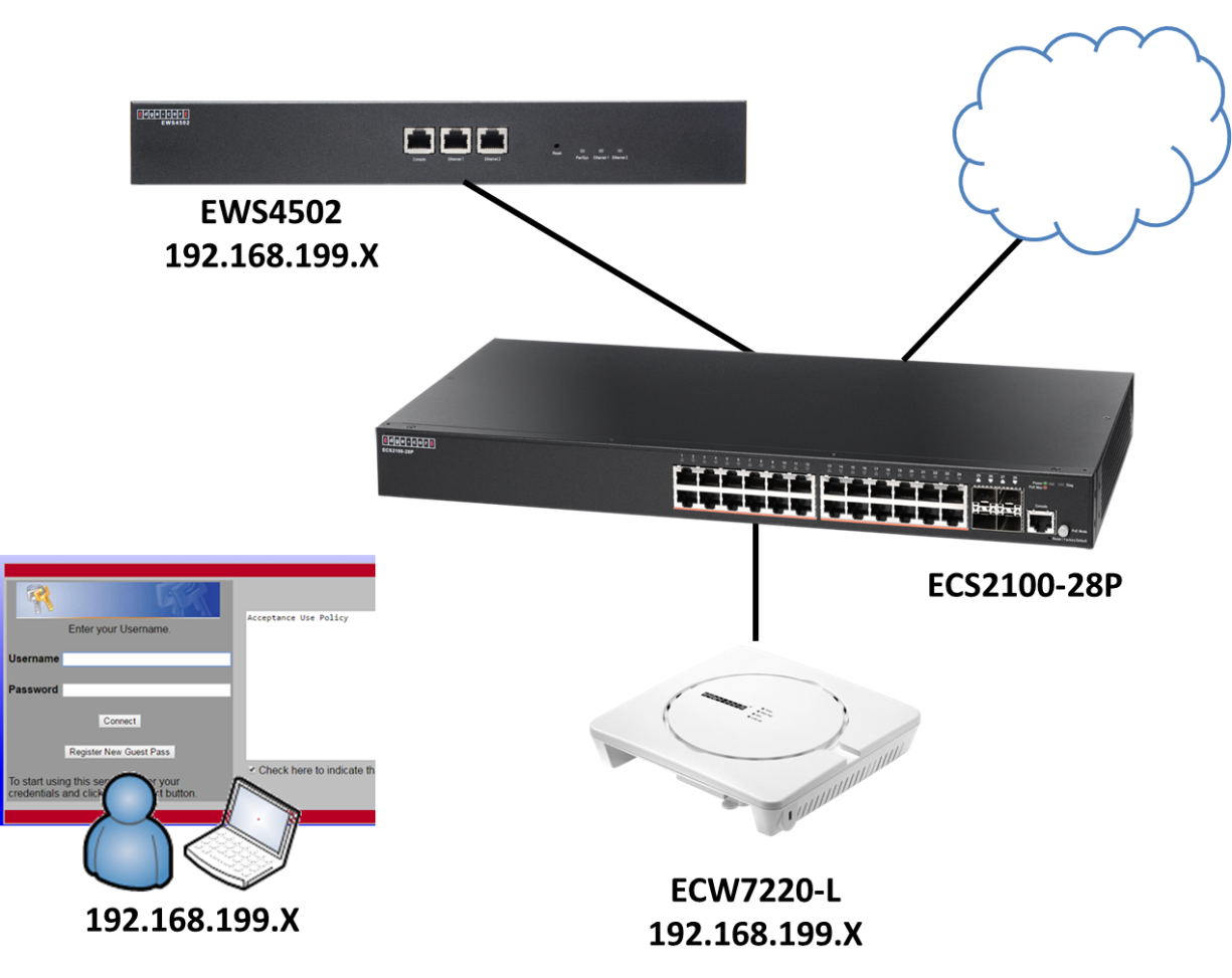
| Access Point | Max transmit power [dBm] | Max Antenna gain (integrated antenna) [dBi] | Can be managed by EWS4502 |
| ECW7220-L | 2.4GHz: 20dBm 5GHz: 20dBm |
2.4GHz: 4dBi 5GHz: 5dBi |
Yes(*) (v1.3.x.x) |
| ECW5320 | 2.4GHz: 27dBm 5GHz: 17dBm |
2.4GHz: 3dBi 5GHz: 4dBi |
No |
| ECW5110-L | 2.4GHz: 20dBm 5GHz: 20dBm |
2.4GHz: 2dBi 5GHz: 3dBi |
Yes(*) (v1.0.x.x) |
| ECW5110 | 2.4GHz: 20dBm 5GHz: 20dBm |
2.4GHz: 2dBi 5GHz: 3dBi |
No |
| ECWO5320 | 2.4GHz: 27dBm 5GHz: 17dBm |
2.4GHz: 5GHz: 12dBi |
No |
| ECWO5110-L | 2.4GHz: 20dBm 5GHz: 20dBm |
2.4GHz: 5GHz: 10dBi |
Yes(*) (v1.0.x.x) |
| ECWO5110 | 2.4GHz: 20dBm 5GHz: 20dBm |
2.4GHz: 5GHz: 10dBi |
No |
(*)Please note that ECW5110-L/ECWO5110-L series it can be managed by EWS4502(v1.0.x.x).
However, if customers would like to manage ECW7220-L, software can be upgrade and it can be managed by EWS4502(v1.3.x.x).
After upgrade, EWS4502 cannot manage ECW5110-L/ECWO5110-L, only ECW7220-L.
So, it means EWS4502 cannot manage ECW5110-L/ECWO5110-L and ECW7220-L at the same time.
ECW7220-L was connected to Access Controller(EWS4502 or EWS4606). The device should be managed by Access Controller centrally.
Why ECW7220-L Wi-Fi function does not work after connecting to Access Controller? The Wi-Fi (2.4G/5G) shows "off"
Why ECW7220-L Wi-Fi function does not work?
The Wi-Fi (2.4G/5G) shows "off"
Symptom of Problem :

Troubleshooting
Step 1:
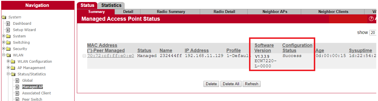
Check and make sure that the status of ECW7220-L is "Managed" by Access Controller.

Step 2:
Check Details of ECW7220-L is following the suggested as shown in following, especially for "Hardware Type" and "Profile".
Mark sure that you select the followings.
Hardware Type: 8-ECW7220-L AP Dual Radio anac/bgn
Profile: 1-Default

*Hardware type : 8 - ECW7220-L AP Dual Radio anac/bgn
*Profile : 1-Default. (This will vary per user's setting) .
For this case, we use default name of profile in Access Controller.
Step 3 :
Check the details of Profile in Access Point Profile List.

Screen capture of the details of Profile shown as following.

Root Cause of problem:
"Hardware Type ID" mismatches in Profile.
Resolution :
Step 1 :
Change Hardware Type ID.

Step 2 :
Apply Profile properly.

Result:
WIFI turns ON.
LEDs (2.4G/5G) turns blue.

Troubleshooting:
How to identify what kind of ''Failure Message''on Configuration Status of ECW7220-L/EWS4502 series and solve it, specific for country code?
1. After the AP managed by AC, but the configuration status still displayed 'Failure'.
System > WLAN > WLAN Configuration > Managed AP > Status > Summary

2. Users can check the reason of failure on the 'Detail!? page, the error is the setting about Country Code.
System > WLAN > WLAN Configuration > Managed AP > Status > Detail

3. Please changes to the correct country code.
System > WLAN > WLAN Configuration > Global > WLAN Switch

Check the country code of ECW7220-L.
Manage > Wireless Settings
*By default, if ECW7220-L has been managed by EWS4502 then web management interface will be disabling.
User may use following command to enable/disable the web interface via CLI.
ECW7220-L-7fa540# set web-server http-status up/down

4. After we change the correct country code, then the configuration will be provision to the AP successfully.
System > WLAN > WLAN Configuration > Managed AP > Status > Summary

The EWS4502 with highest priority in the same cluster becomes the Cluster Controller.
If the priority is the same, the switch with lowest IP address will be the Cluster Controller.
And the highest cluster priority is 255.
AC cluster Scenario

How to configure the cluster priorty
Manage Page: System > WLAN > WLAN Configuration > Global
1. Configure the cluster priority of EWS4502-1 192.168.1.30 to 255.
*The highest cluster priority is 255, thus EWS4502-1 will become the Cluster Controller.

2. Configure the cluster priority of EWS4502-2 192.168.1.31 to 1.

How to check and ensure the cluster priority applied
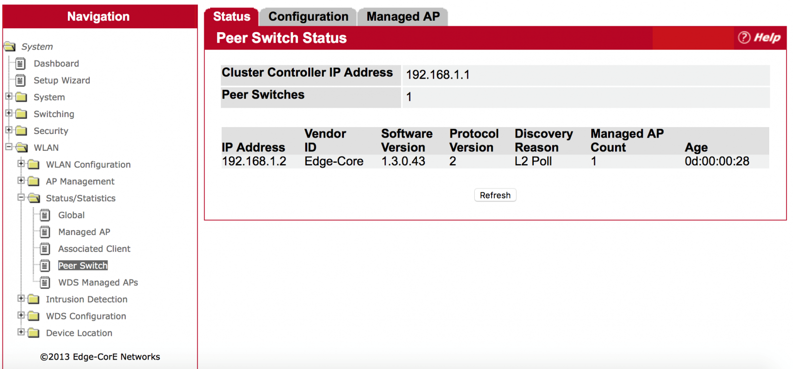
Manage Page: System > WLAN > Status/Statistics > Peer Switch
Users can know which AC is the current cluster controller and which AC will manage AP.
1. Peer switch status of Cluster Controller EWS4502-1 192.168.1.30.

2. Peer switches status of slave AC ECW4502-2 192.168.1.31.
*By default, AP will be managed by AC Controller first.

Troubleshooting
Q: Why Cluster Controller and Slave AC displayed the same AP?
Manage Page: System > WLAN > Status/Statistics> Managed AP


A: The Cluster Controller collects status and statistics from all the other AC in the cluster, including information about the APs peer switches manage and the clients associated to those APs.
Thus if the AP managed by Slave AC then the user will see this situation.
*By default, AP will be managed by AC Controller first.
Q: What kind of situation the AP will be managed by Slave AC?
A: The users configure the AP to find the Slave AC to manage first.
For Example:
- Users specify the IP address of AC manually.
- AP obtains the IP address of AC from the DHCP server. (Option 43)
Q: Why Cluster Controller and Slave AC displayed the same AP?
Manage Page: System > WLAN > Status/Statistics> Managed AP


A: The Cluster Controller collects status and statistics from all the other AC in the cluster, including information about the APs peer switches, which manage the clients associated to those APs.
Thus if the AP managed by Slave AC, the user will see this situation.
*By default, AP will be managed by AC Controller first.
Q: Under which of situation, the AP will be managed by Slave AC?
A: The users configure the AP to be managed by Slave AC as the first priority.
For Example:
- Users specify the IP address of AC manually.
- AP obtains the IP address of AC from the DHCP server. (Option 43)


Wireless Controller: EWS4502, Fit AP: ECW5110-L
Part 1: Fit AP Installation
1. Assign IP address to all the Fit AP via DHCP Server otherwise need specify static IP to them:
~ # cli
Edge-Core# config
Edge-Core(config)# interface ethernet
Edge-Core(if-ethernet)# ip address 192.168.1.20 255.255.255.0 192.168.1.1
Edge-Core(if-ethernet)# exit
Edge-Core# copy running startup
2. If the fit AP not within the wireless controller network, then need specify the wireless controller IP address to them. You can specify the wireless controller IP address via WEB UI:


You can specify the wireless controller IP address via CLI:
~ # set_sys_ac_ip_primary 192.168.1.10
~ # cli
Edge-Core# copy running startup:
Or you can use DHCP options 138 to assign the wireless controller IP address to Fit AP.
Part 2: Setup Wireless Controller to Manage Fit AP at Central Office
1. Specify IP address to wireless controller via CLI:
(EdgeCore Switching) >enable
(EdgeCore Switching) #network protocol none
(EdgeCore Switching) #network parms 192.168.1.10 255.255.255.0 192.168.1.1
2. System>Setup Wizard>Global -> Set the correct 'Country Code'


3. System>Setup Wizard>AP Image -> Select corresponding 'HW Type' and set currently AP software version to 'Software Version'


4. You can modify 'Default' AP profiles at here
System>Setup Wizard>Profile


System>Setup Wizard>Radio


System>Setup Wizard>VAP


5. System>Setup Wizard>Valid AP -> Set Fit AP MAC address as valid AP and assign 'Default' AP profile to it


Part 3: Setup Wireless Controller to Manage Fit AP at Branch Office
1. WLAN>WLAN Configuration>Networks -> Create new VAP


2. WLAN>WLAN Configuration>AP Profiles -> Create new AP Profiles 'Taipei' and 'Tainan'


3. WLAN>WLAN Configuration>AP Profiles>Taipei/Tainan >VAP -> Replace default VAP to new VAP


4. WLAN>WLAN Configuration>Intrusion Detection>AP Authentication Failures -> Press 'Manage' button to set all Fit AP to Valid AP with default AP profile


5. WLAN>WLAN Configuration>Local AP Database -> Go to check new Valid AP, assign new profile to the Fit AP


Final Results
WLAN>Status/Statistics>Managed AP -> Check the Fit AP Status


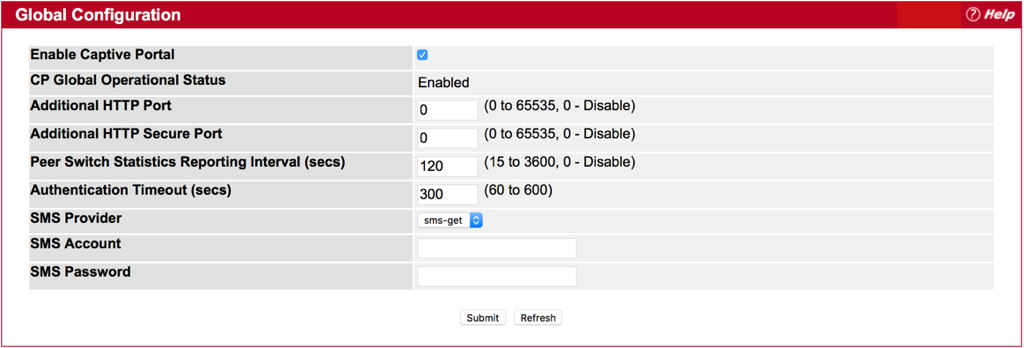
Setup Captive Portal Self-Service Local mode with SMS
1. Enabled Captive Portal and select the SMS provider, then fill out SMS account and password.
System > Security > Captive Portal> Global Configuration
.png)
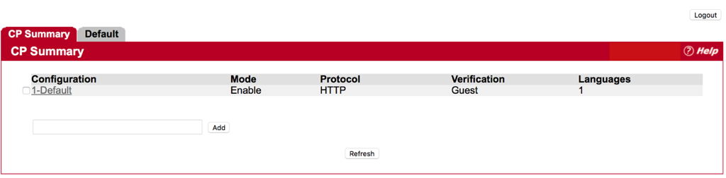
2. You can use the Default configuration or create a new one.
System > Security > Captive Portal> CP Configuration > CP Summary
.png)
3. Set Verification Mode as “Self-Service Local” and Notification Method as “SMS” in the CP Configuration page.
System > Security > Captive Portal> CP Configuration > Default
.png)
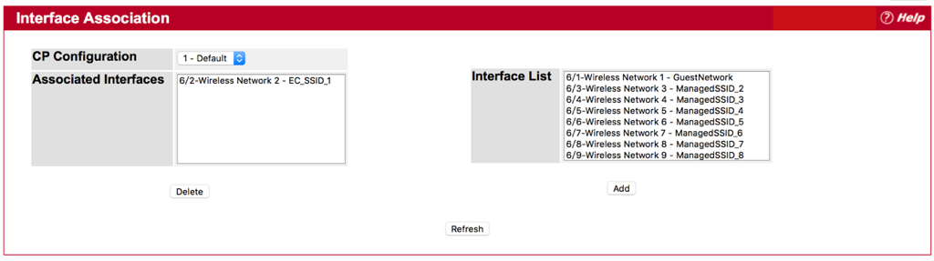
4. Add the VAP to associated Interface in Interface Association page
System > Security > Captive Portal> Interface Association
.png)
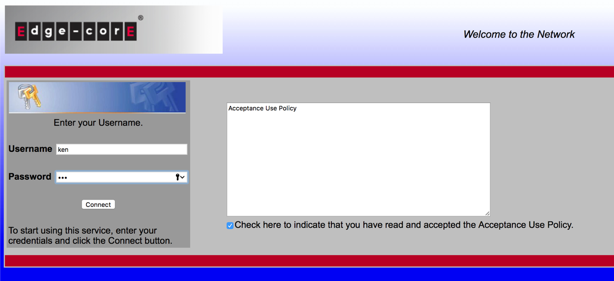
5. When the client want to access to internet, AC will let the client redirect to the authentication page of captive portal.
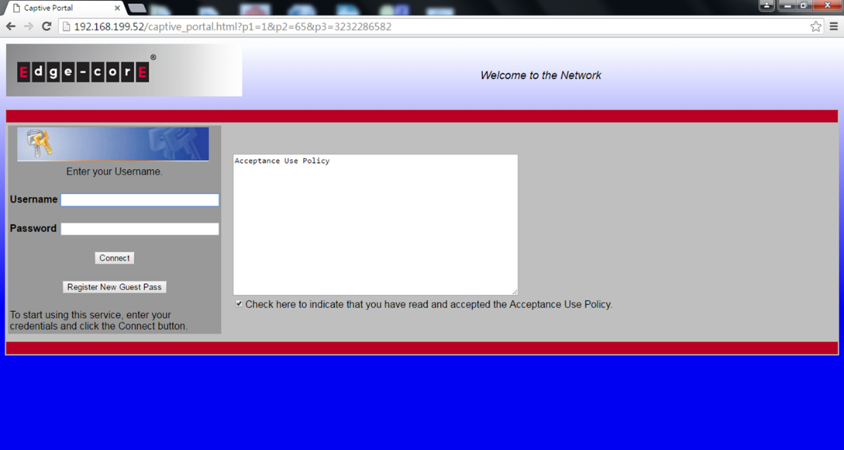
6. Client has to fill out the username and mobile number to register an account.
*Email address is optional, client can choose fill out or not.
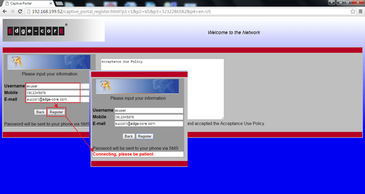
7. After the registration is complete, client will receive the password of SMS from the SMS provider.
*The password is generating by AC randomly, the SMS provider only forward the password to the wireless client.
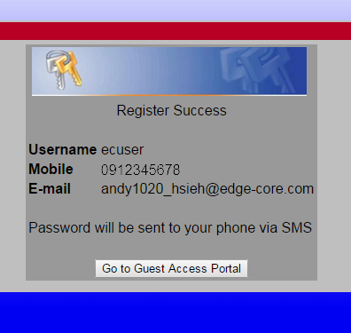
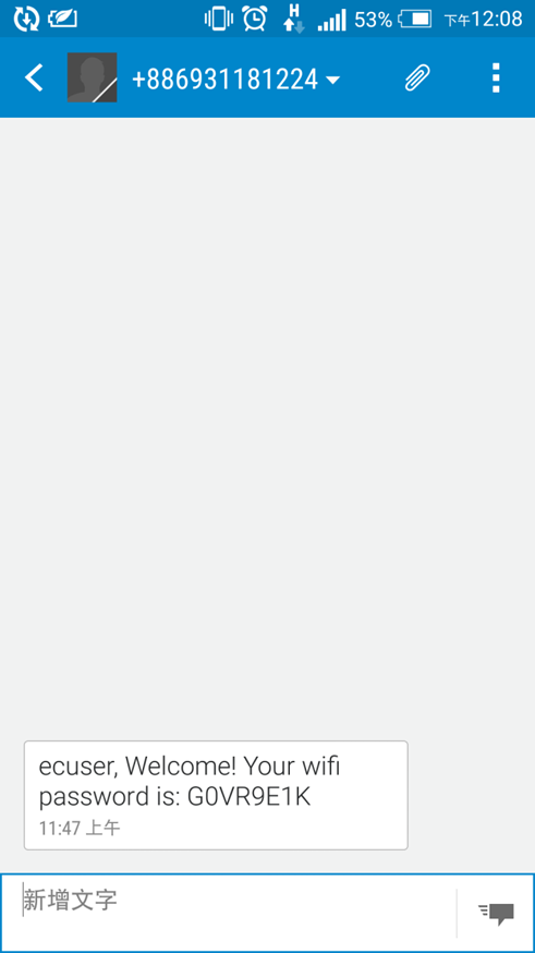
8. Enter the username and password to complete the authentication.
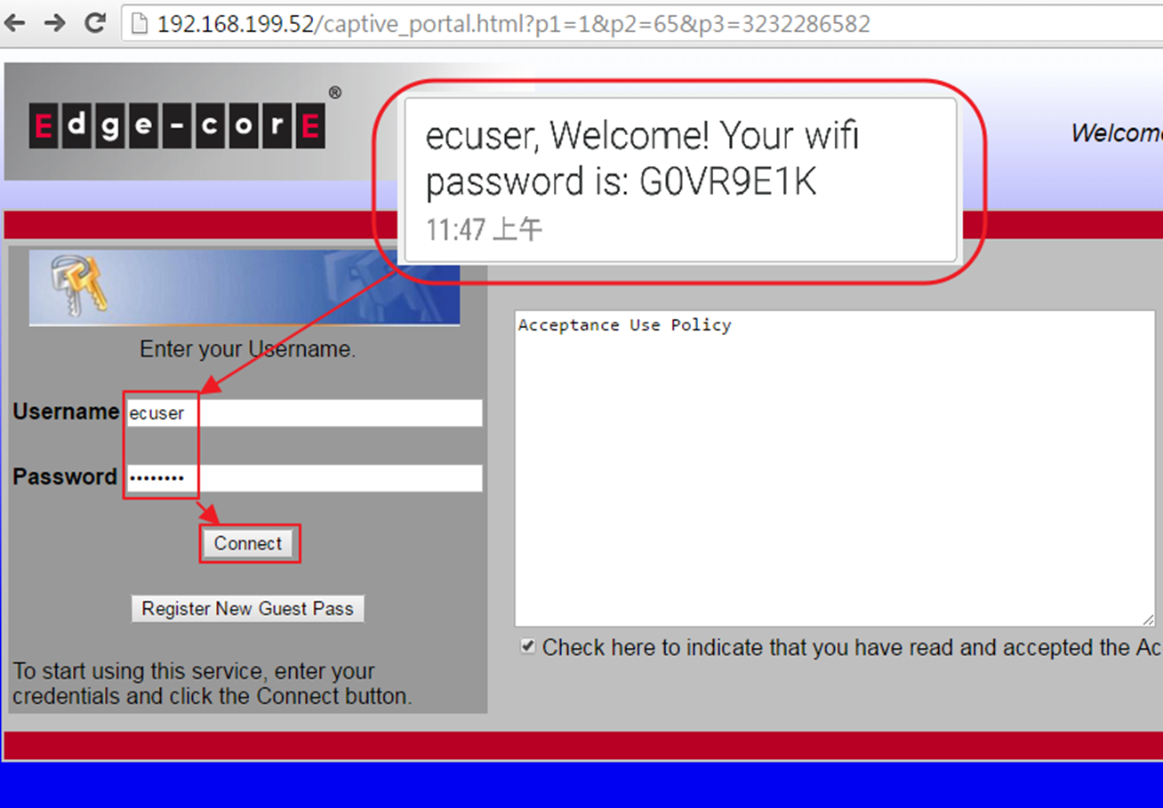
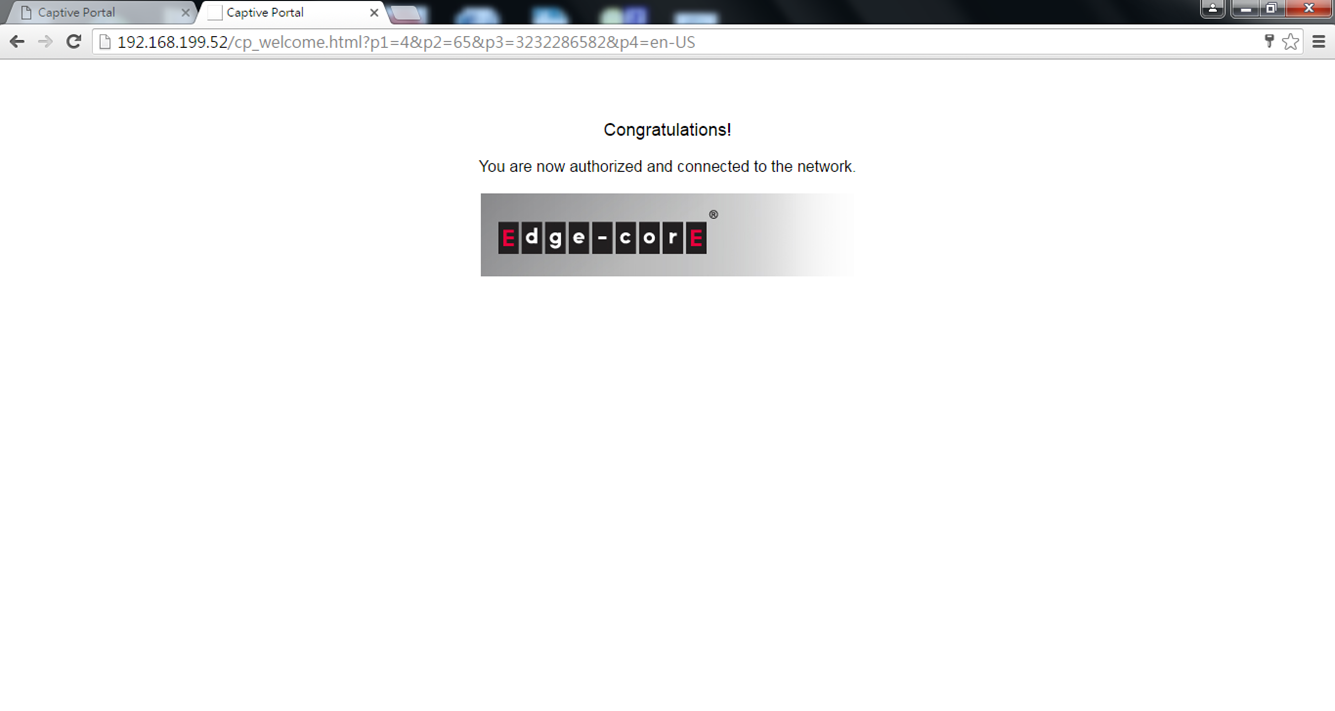
9. Wireless client will be able to access internet.
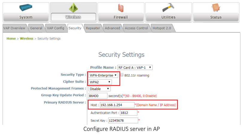
Step 1 : Fill-in RADIUS Server’s IP Address, and then press submit button.
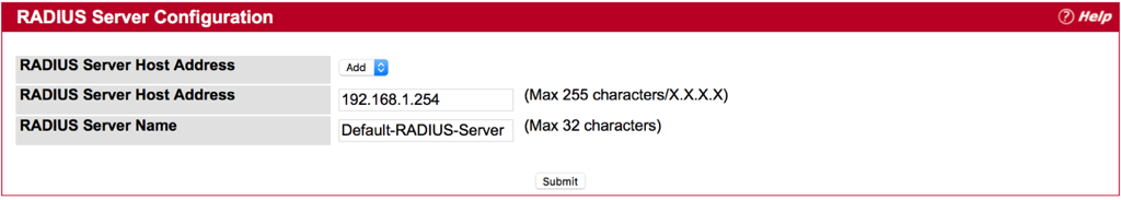
Step 2 : Check the box of Apply
Step 3 : Fill-in text string for Secret , and then press Submit
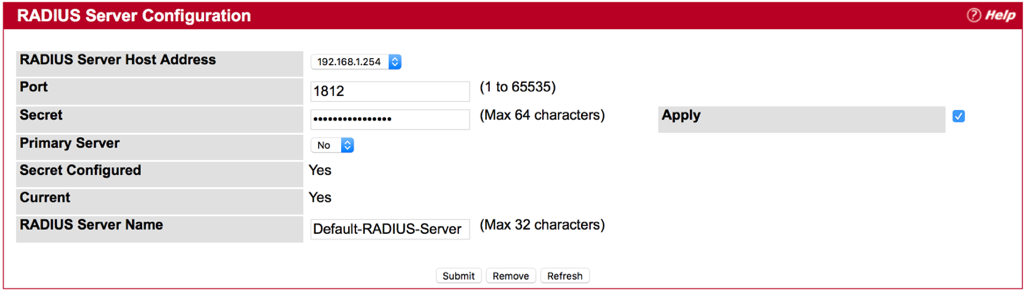
Notes:
- Secret - Shared secret text string used for authenticating and encrypting all RADIUS communications between the device and the RADIUS server. This secret must match the RADIUS encryption. The name contain up to 64 characters. The secret key cannot include sixteen continuous star(*) characters.
- Apply : The Secret will only be applied if this box is checked. If the box is not checked, anything entered in the Secret field will have no affect and will not be retained. This field is only displayed if the user has READWRITE access.
- Please make sure your RADIUS Server configure properly on EWS4502.
- Configure Capital Portal with RADIUS authentication on EWS4502
- Global Configuration
- CP Configuration
- Interface Association
- Result
- Please make sure your RADIUS Server configure properly on EWS4502 before you start the next step. Please refer to FAQ “How to configure RAIUD Server on EWS4502” for more information.
- Configure Capital Portal with RADIUS authentication on EWS4502
- Global Configuration
Step 1 : Check the box of “Enable Captive Portal” and press Submit button.
- CP Configuration
Step 1 : Click “Default”
Step 2 : Change Verification Mode to RADIUS
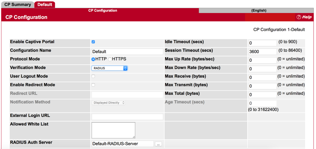
*Make sure the name of RADISU Auth Server is the same as RADIUS Server Name that we set before. (Refer to FAQ “How to configure RAIUD Server on EWS4502”.)
Step 3 : Press Submit button and Check Configuration.
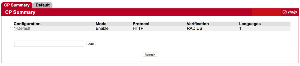
- Interface Association
Step 1 : Choice and Add one SSID for CP Configuration from Interface List.
- Result
Authentication is successful.
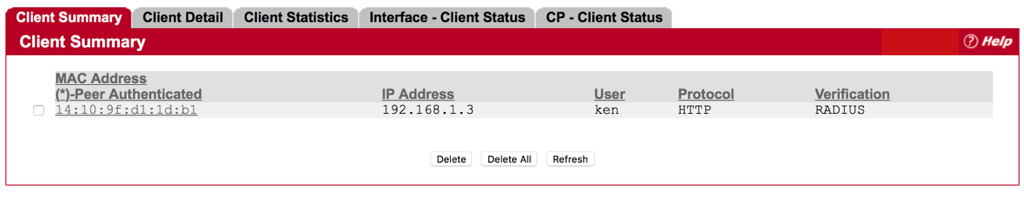
Administrator is able to get client information from EWS4502.
System -> Security -> Captive Portal -> Client Connection Status
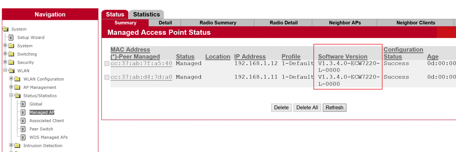
1. ECW7220-L is managed by EWS4502.
2. Specify the ECW7220-L image name. You may enter up to 32 characters, and the file extension “.tar” must be included. (ex: apimage-3.tar)
3. Upload the image file to TFTP server.
4. Fill in the TFTP server address and image3’s file name. The image3 option is correspond with ECW7220-L. WLAN -> AP Management -> Software Download
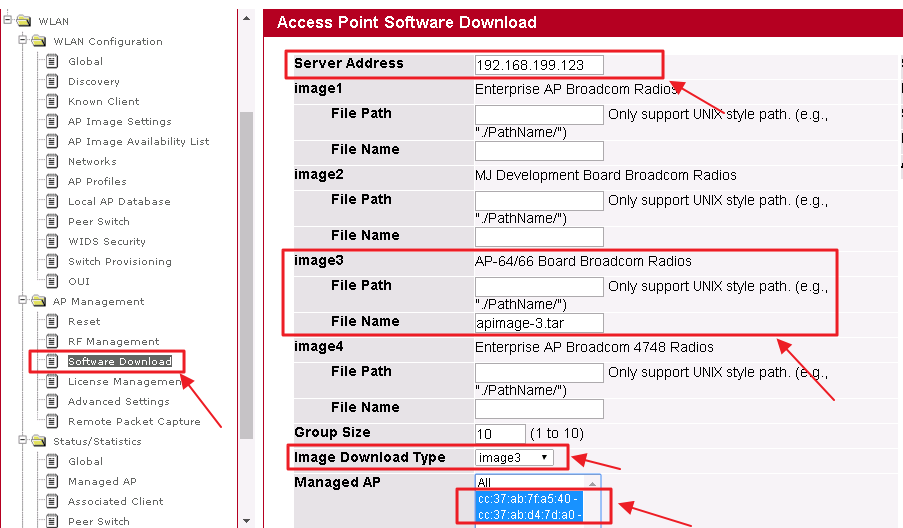
5. Select the “image download type” to imange3 and managed AP, then click the Start button. APs will start the firmware upgrade via TFTP server. WLAN -> AP Management -> Software Download
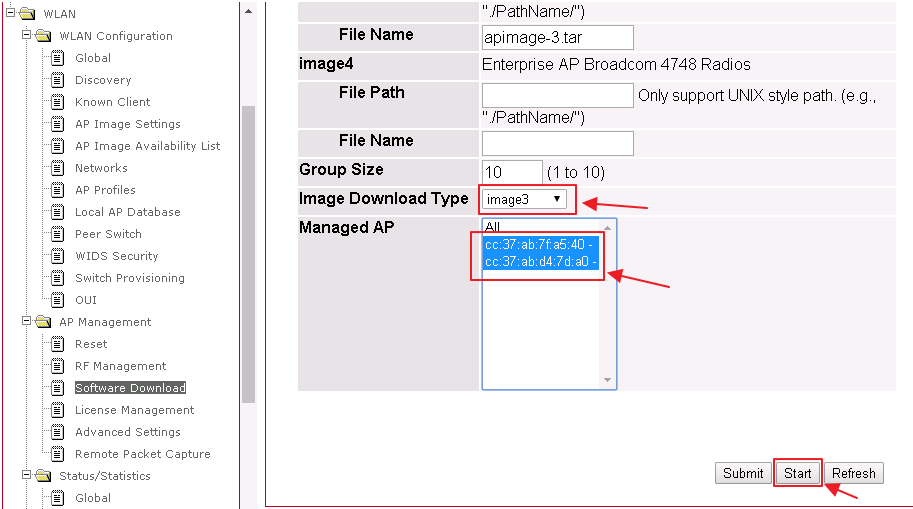
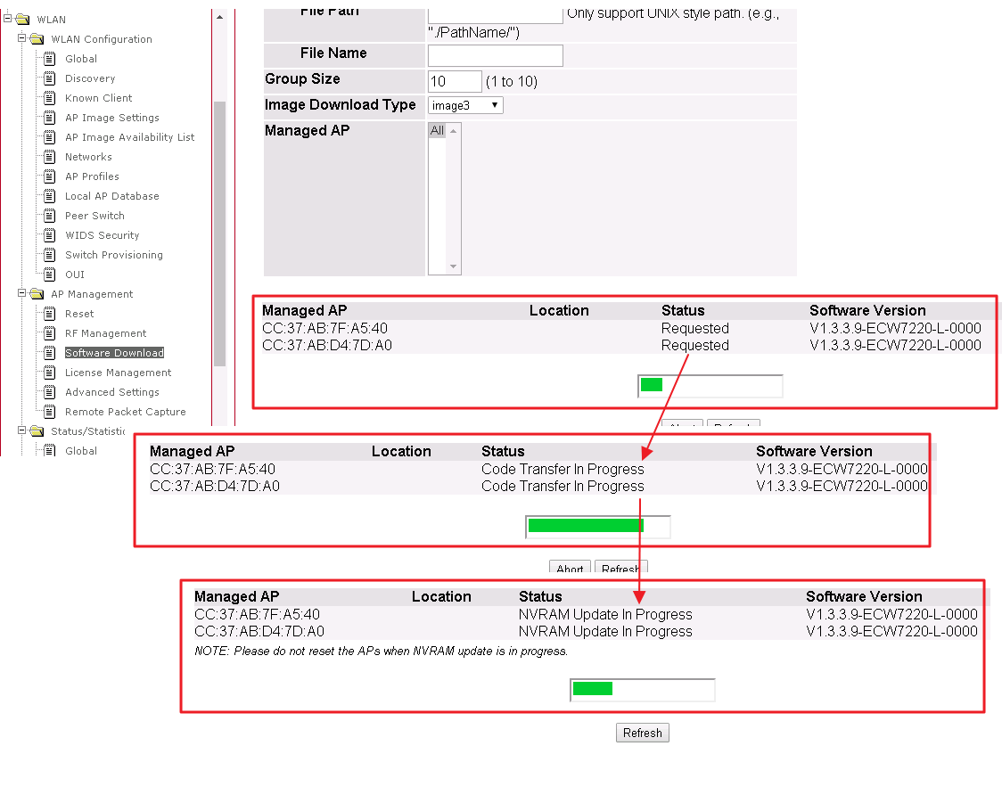
6. Users will see the firmware upgrade status.
WLAN -> AP Management -> Software Download
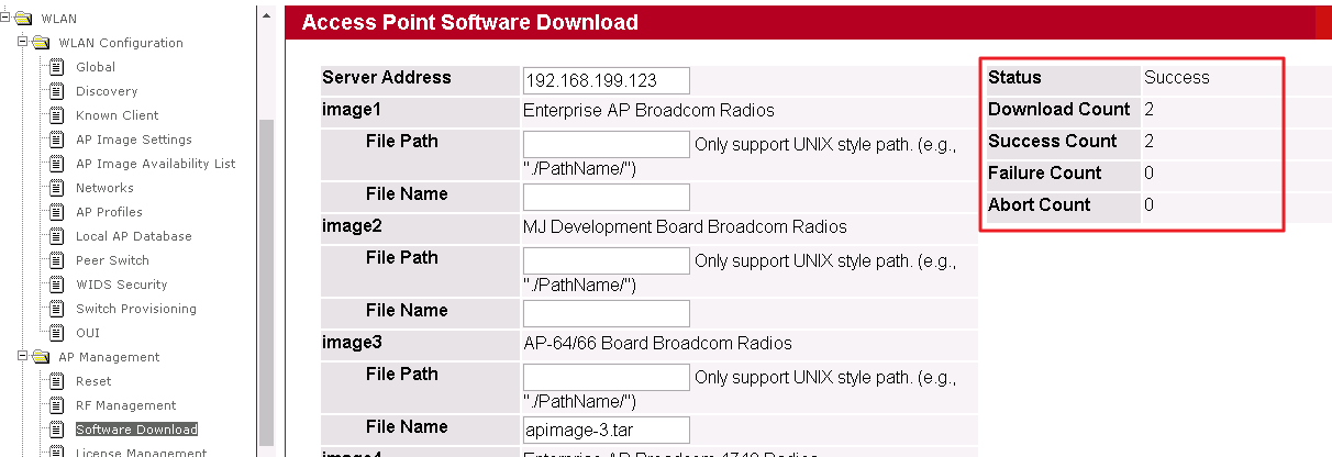
7. When the upgrade process is completed and the status will show “Success”.
WLAN -> AP Management -> Software Download
8. Users can check status in EWS4502 web UISystem -> WLAN -> Status/Statistics -> Managed AP -> Software Version
1. ECW7220-L is managed by EWS4502
2. Modify ECW7220-L image name to apimage-3.tar
3. Upload apimage-3.tar file to TFTP server
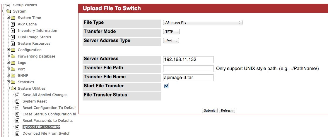
4. Upload ECW7220-L image to EWS4502System -> System Utilities -> Upload File to switch -> Select File Type to “AP Image File”
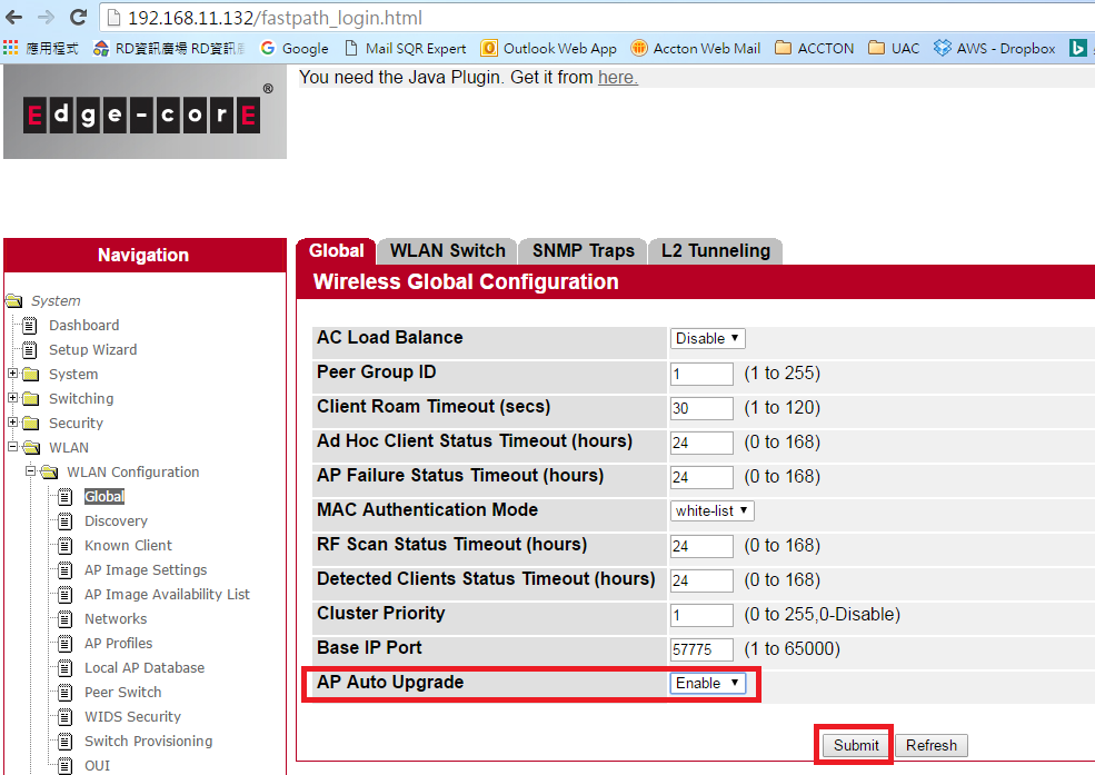
5. Enable “AP Auto Upgrade” function in AC web UISystem -> WLAN -> WLAN Configuration -> Global -> AP Auto Upgrade -> Enable
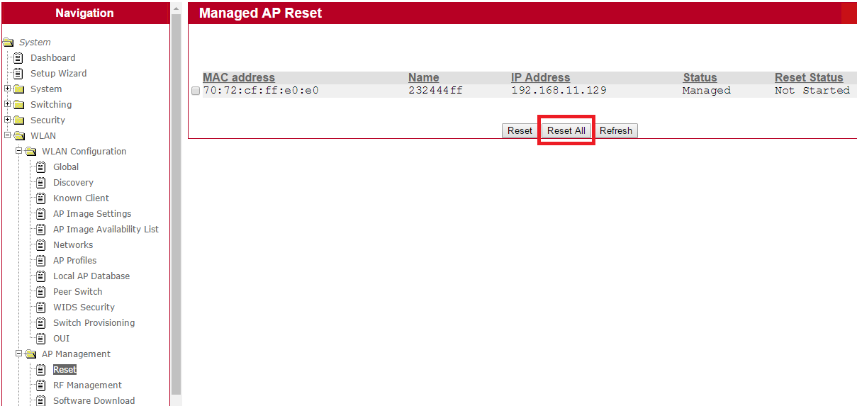
6. Click “Reset All” to start ECW7220-L upgrade process in EWS4502 web UISystem -> WLAN -> AP Management -> Reset -> Reset All
7. User can check upgrade status in EWS4502 web UISystem -> WLAN -> Status/Statistics -> Managed AP -> Software Version
Suggest the user modify the cluster priority to be higher on one AC to be the cluster master.
If the 2 AC are in the same broadcast domain, you can see the Peer switch info.
(WLAN -> Status/Statistics -> Peer Switch)
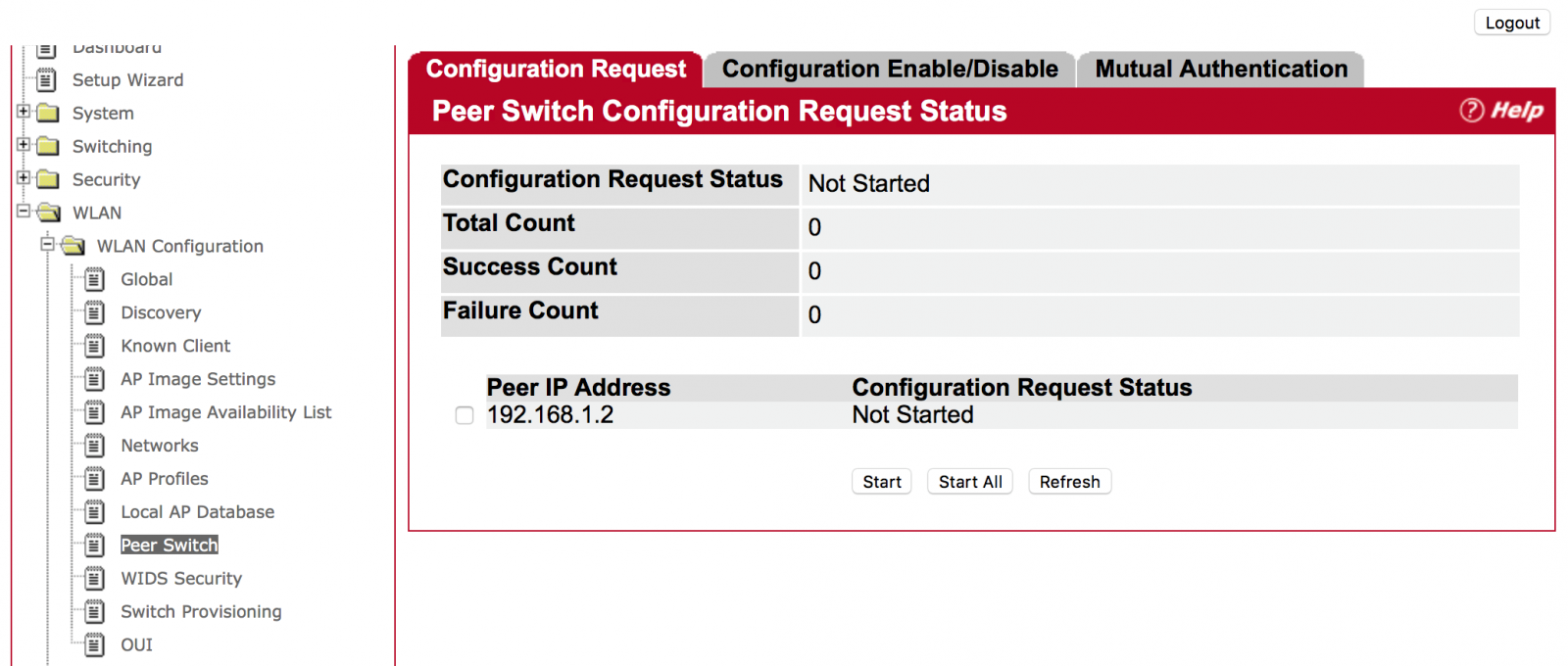
(WLAN -> WLAN Configuration -> Peer Switch)
Choose one of the peer switches and press the “Start” Button. (Use “Start All” for all peer switches)
Answer: On the Web page
Step 1: Click “WLAN” then “WLAN Configuration”, then “AP Image Availability List”
Then, user will find the AP image. Filename “apimage-3.tar” is for ECW7220-L.
.png)
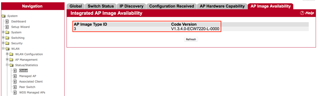
Step 2: Check “WLAN”, then “Status/Statistics”, then “Global”, then
In “AP Image Availability”, users will find the code version on the page.
Answer:
The Wireless Access Controller can create multiple SSIDs for each AP. Total 225 SSIDs and 127 Profiles can be created. Each AP can support 32 SSIDs with 16 for 2.4G and 16 for 5G, while Wireless Access Controller can manage multiple Access Points with different profile and SSID.
Description
Impact on Edgecore Access Point
WPA-2 vulnerabilities will not affect the following products because those models do not support WDS.
ECW7220-L
ECW7220-L EU
ECW7220-L TR
SMC2890W-AG
SMC2891W-AG
For WPA-2 vulnerabilities affected products, Edgecore Networks engineering team are working on the software upgrade to fix the issues with the following estimated schedule.
End of November
SMC2890W-AN
SMC2891W-AN
Middle of December
ECW5110
ECW5212
ECW5320
ECWO5110
ECWO5320
Before the availability of the new fixed software, we strongly recommend users to turn off WDS modes if you turn on the mode. WDS mode is defaulted "off" when the product delivered from the factory.
Please refer to the following link to FAQ : How to turn off WDS mode?
- Figure1:
- Figure 2:
- Figure3:
- Group: the Group that the clients will be assigned to after successful login, which will have a Policy profile mapping to the specific Service Zone applied
- Guest Information: includes account email and answers to the questionnaire (if enabled), which can be viewed and downloaded for purposes such as network monitoring, data analysis or marketing. Entries will not be cleared automatically, but an email notification can be sent when there are 1000 entries remaining (11000/12000, maximum is 12000 entries)
- Delete All: allows administrators to delete all the stored data; administrators can delete all entries after export to keep the list up-to-date.
- Questionnaire: provides administrators an option to show questions on the login page, data collected from the questionnaire can be viewed in Guest Information
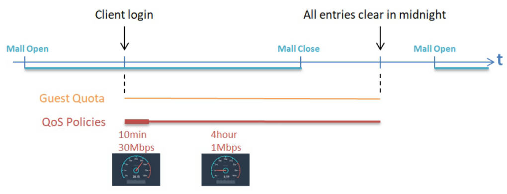
- Guest Access Time: allows administrators to define a usage time constraint based on MAC addresses
- 1 Day Access: clients are enforced with a usage time constraint
- Multi-Day Access: clients are enforced with a usage time constraint
- Quota: the permitted duration and volume for each client
- Reactivation (1 Day Access only): the time period after a session expires that the clients have to wait before they can request a new session
- Access Limit (1 Day Access only): how many times a device can request for a free account per day
- Email Verification: can be enabled to ensure that the entered email is a valid email address. Clients have to activate their account within the activation time to extend their usage time by clicking a link in the mail sent by the mail server. Note that the activation is merely a timer and does not add to the account’s Quota
- SMTP Server Settings: to assign SMTP server for sending the mail for redeem clients. This SMTP is shared with Guest Email Verification. Please refer to “SMTP Setting paragraph below”. Taking Gmail as SMTP server, the configurations are
- SMTP port: 465
- Encryption: SSL
- Authentication: Login: Account Name: admin’s Gmail email address
- Authentication: Login: Password: admin’s Gmail email’s password
- Sender Email Address: admin’s Gmail email address
- Sender Name: the Sender Name displayed in the client mail box.
- Activation Email Subject: customizable email subject displays in the client mail box
- Activation Email Content: customizable email content displays in the client mail box (max. 2000 characters)
- Activation Link: the name with hyperlink to redeem the account in the client email content
- Guest Quota List: displays how many allowances are remaining for the access-limited Guest accounts by MAC address and Email Address. (It would be automatically refreshed daily at the midnight, and the oldest entries are removed when reaching maximum).
- Email Denial List: checks the email domains for login permission, if prevention of junk mailboxes is desired
The Sender Name, Email Subject, and Email Content (max. 2000 characters) are all customizable as soon as the SMTP server is ready. SMTP server configuration is done by clicking the “Assign SMTP Server” button.
SMTP Settings
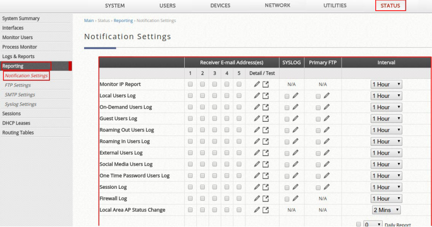
Allows the configuration of 5 recipient E-mail addresses and necessary mail server settings where various user related logs will be sent to.
- SMTP Server: enter the IP address of the sender’s SMTP server.
- SMTP Port: the port number is 25 by default. Administrator can specify it to be another port number if the SMTP server runs SMTP over SSL.
- Encryption: enable this option if your SMTP server runs SMTP over TLS or SSL.
- Authentication: the system provides four authentication methods, Plain, Login, CRAM-MD5 and NTLMv1, or None to use none of the above. Depending on which authentication method is selected, enter the Account Name, Password and Domain.
- CRAM-MD5 is a standardized authentication mechanism. This is used by Pegasus although the method to be used cannot be configured.
- Login is a Microsoft’s proprietary mechanism and uses UNIX login and password. Outlook and Outlook express use Login as default, although they can be set to use NTLMv1. It is used by Pegasus although the method to be used cannot be configured.
- NTLMv1 is a Microsoft’s proprietary mechanism that is not currently available for general use.
- Sender E-mail Address: the e-mail address of the administrator in charge of the monitoring. This will show up as the sender’s e-mail address.
- Receiver E-mail Address (1 ~ 5): up to 5 E-mail addresses can be set up here to receive notifications.
- Send Test E-mail: administrators can send a test email into the receivers’ mailbox following above configuration when setting up the SMTP server for the first time
- SMTP server address: smtp.gmail.com
- SMTP port: 465
- Encryption: SSL
- Authentication: Login: Account Name: admin’s Gmail email address
- Authentication: Login: Password: admin’s Gmail email’s password
- Sender Email Address: admin’s Gmail email address
1. Using the Wireless Controller as an external RADIUS server (Local and/or On-Demand databases) for a remote gateway
2. Using the Wireless Controller as a RADIUS server in 802.1X authentication (transparent login)
Note that for the first scenario, the remote gateway can be an Edgecore Wireless Controller or a third-party controller, and multiple remote gateways can be setup. Detailed configuration are shown in the following chapters.
This technical guide provides the administrator with instructions on how to setup the scenarios above for different applications. Verification from the client side is also shown in the end of the document. Click here to download the Technical Guide!
This technical guide should help network administrators to easily setup and configure bandwidth limitation for all users in the network. Click here to know how to setup the User Bandwidth Throttling.
There are multiple types of logs and reports in the Controller, as described in the following:
a. CAPWAP Log
b. Configuration Change Log
c. Local Monthly Usage
d. Local Web Log
e. Micros Opera Log
f. On-Demand Billing Report
g. RADIUS Server Log
h. SIP Call Usage Log
i. SMS API Log
j. System Log
k. UAMD Log
l. User Events
Click “product selector tool”
to help you to find what you need.